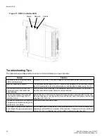
background image

iWorx® HPU3

Printed in the USA

iWorx® and iView® are registered trademarks of Taco Electronic Solutions, Inc. 

© 2015 Taco Electronic Solutions, Inc. 

LON, LONWORKS, & LONMARK are trademarks of Echelon Corporation

C

ONTROLS 

M

ADE 

E

ASY

®

Taco Electronic Solutions, Inc.

, 1160 Cranston Street, Cranston, RI 02920 

Telephone: (401) 942-8000 FAX: (401) 942-2360.

Taco (Canada), Ltd.

, 8450 Lawson Road, Unit #3, Milton, Ontario L9T 0J8. 

Telephone: 905/564-9422. FAX: 905/564-9436.

Taco Electronic Solutions, Inc. is a subsidiary of Taco, Inc. 
Visit our web site at: 

http://www.taco-hvac.com

Taco Electronic Solutions, Inc. (TES) will repair 
or replace without charge (at the company's 
option) any product or part which is proven 
defective under normal use within one (1) year 
from the date of start-up or one (1) year and six 
(6) months from date of shipment (whichever 
occurs first).

In order to obtain service under this warranty, it 
is the responsibility of the purchaser to 
promptly notify the local TES stocking distribu-
tor or TES in writing and promptly deliver the 
subject product or part, delivery prepaid, to the 
stocking distributor.   For assistance on war-
ranty returns, the purchaser may either contact 
the local TES stocking distributor or TES.  If the 
subject product or part contains no defect as 
covered in this warranty, the purchaser will be 
billed for parts and labor charges in effect at 
time of factory examination and repair.

Any TES product or part not installed or oper-
ated in conformity with TES instructions or 
which has been subject to accident, disaster, 
neglect, misuse, misapplication, inadequate 
operating environment, repair, attempted 
repair, modification or alteration, or other 
abuse, will not be covered by this warranty.

TES products are not intended for use to sup-
port fire suppression systems, life support sys-
tems, critical care applications, commercial 
aviation, nuclear facilities or any other applica-
tions where product failure could lead to injury 
to person, loss of life, or catastrophic property 
damage and should not be sold for such pur-
poses.

If in doubt as to whether a particular product is 
suitable for use with a TES product or part, or 
for any application restrictions, consult the 
applicable TES instruction sheets or in the U.S. 
contact TES at 401-942-8000 and in Canada 
contact Taco (Canada) Limited at 905-564-
9422.

TES reserves the right to provide replacement 
products and parts which are substantially sim-
ilar in design and functionally equivalent to the 
defective product or part.   TES reserves the 
right to make changes in details of design, con-
struction, or arrangement of materials of its 
products without notification.

TES OFFERS THIS WARRANTY IN LIEU OF 
ALL OTHER EXPRESS WARRANTIES.  ANY 
WARRANTY IMPLIED BY LAW INCLUDING 

WARRANTIES OF MERCHANTABILITY OR 
FITNESS IS IN EFFECT ONLY FOR THE 
DURATION OF THE EXPRESS WARRANTY 
SET FORTH IN THE FIRST PARAGRAPH 
ABOVE.

THE ABOVE WARRANTIES ARE IN LIEU OF 
ALL OTHER WARRANTIES, EXPRESS OR 
STATUTORY, OR ANY OTHER WARRANTY 
OBLIGATION ON THE PART OF TES.

TES WILL NOT BE LIABLE FOR ANY SPE-
CIAL, INCIDENTAL, INDIRECT OR CONSE-
QUENTIAL DAMAGES RESULTING FROM 
THE USE OF ITS PRODUCTS OR ANY INCI-
DENTAL COSTS OF REMOVING OR 
REPLACING DEFECTIVE PRODUCTS.

This warranty gives the purchaser specific 
rights, and the purchaser may have other rights 
which vary from state to state.  Some states do 
not allow limitations on how long an implied 
warranty lasts or on the exclusion of incidental 
or consequential damages, so these limitations 
or exclusions may not apply to you.

LIMITED WARRANTY STATEMENT

Summary of Contents for iWorx HPU3

Page 1: ...evice 6 Routing Cabling to the Device 7 Grounding the Device 7 Wiring Information 8 Connecting Input Devices 9 Connecting Output Devices 10 Other Connections 11 Specifications 11 Electrical 11 Mechani...

Page 2: ...iWorx HPU3 2 505 035 Effective June 30 2015 2015 Taco Electronic Solutions Inc THIS PAGE LEFT BLANK INTENTIONALLY...

Page 3: ...tem for monitoring and control applications Features Two stage compressor heating cooling control Reversing valve control Auxiliary Emergency Heat enable Dehumidification with Reheat both internal and...

Page 4: ...hvac com APPLICABLE DOCUMENTATION See the table below for additional documentation that may be applicable to this controller Description Audience Purpose iWorx LCI Application Guide Docu ment No 505 0...

Page 5: ...ital device pursuant to Part 15 of the FCC rules These limits are designed to provide reasonable protection against harmful interference This equip ment can radiate radio frequency energy and if not i...

Page 6: ...Volts AC To calculate power source current requirements add the power consumption of all peripheral devices to that of the controller The controller and sensor power supplies can use the same power s...

Page 7: ...control enclosure and wiring conduit Grounding the Device The ground terminal T40 must be securely connected to earth ground Failure to properly ground this equipment will result in improper operation...

Page 8: ...ons Inc WIRING INFORMATION WARNING Terminals 6 9 and 12 are connected internally on all HPU3 controllers Disconnect ALL power sources when installing or servicing this equipment to prevent electrical...

Page 9: ...connect the heat pump thermostat or an RH humidity sensor to the unit attach one wire from the thermostat or sensor to STAT T3 and the other wire to the adjacent common T4 Equipment Status EQS To con...

Page 10: ...e SAT optional To connect a thermistor Precon III to the analog input attach one wire of the sensor to ST T13 and the other wire to the adjacent common T12 Connecting Output Devices Stage 1 Stage 2 S1...

Page 11: ...wire from a 24 VAC power supply to PWR T39 and the other output wire from the power supply to the adjacent common terminal T38 T38 must be connected to earth ground Ground GND Terminal GND T40 must b...

Page 12: ...ters For detailed specifications refer to the FTT 10A Free Topology Transceiver User s Guide published by Echelon Corpo ration www echelon com support documentation manuals transceivers Mechanical Hou...

Page 13: ...control algorithm to minimize excessive cycling As the temperature decreases below the cooling setpoint the compressor stages are sequenced off When the unoccupied mode is entered the cooling setpoint...

Page 14: ...l alarm is reported to the LCI When the zone humidity rises above the humidity setpoint dehumidification is enabled by activating the dehumidifica tion output external dehumidification and optionally...

Page 15: ...point offset also affects the calculated heating and calculated cooling setpoints by an equal amount The set point offset only applies in the occupied mode of operation it has no affect in the unoccup...

Page 16: ...erature drops below the calculated heating setpoint the reversing valve is cycled to the heating position When the space temperature drops below the calculated heating setpoint minus the heating con t...

Page 17: ...e temperature is less than the space setpoint If the temperature rises above the space setpoint then the minimum on and off times are ignored When the space temperature rises above the space setpoint...

Page 18: ...ling setpoint for a predefined time period the last energized stage is turned off Note that the last stage that was turned on will be the first one to be turned off If the space tem perature remains b...

Page 19: ...1 On T1 T2 T1 T2 Reversing Valve COOL Cooling Sequence Unoccupied Mode Commissioning The controller has a Commissioning screen that allows any of the controller s outputs to be manually configured to...

Page 20: ...after dehumidification occurs Dehumidification begins when the Space Humidity rises above the configured dehumidification setpoint and stops when the Space Humidity falls three percent below the dehu...

Page 21: ...o zero percent humidification is not enabled Thermostat Space temperature current humidity setpoint adjustment fan auto on status depending on the thermostat model and occupancy override request are m...

Page 22: ...ly closed active when open When a pressure alarm input becomes active a high or low pressure alarm message is sent to the LCI and the heat pump outputs are disabled When the pressure alarm clears norm...

Page 23: ...n the HPU3 with LNS or other LONWORKS tools if they wish The LCI also provides network supervision of the HPU3 The LCI periodically sends a ping message to the HPU3 which elicits a response If the res...

Page 24: ...go beyond the Supply RH Limit nviSetpoint overrides the setpoint as obtained from the thremostat SLink or BZU LCI or a pre configured backup schedule nviOccCmd overrides the occupancy as obtained fro...

Page 25: ...iResetRuntime SNVT_lev_disc 0 no reset 1 reset runtimes Resets fan heating and cooling runtimes nviSysTime SNVT_time_stamp Date Time System time nviUnitEnable unsigned byte 0 Off 4 On 1 no effect Unit...

Page 26: ...ature Space Humidity 0 to 100 Space Humidity Supply Air Temp 22 F to 122 F 30 C to 50 C Supply Air Temperature Supply Air Humidity 22 F to 122 F 30 C to 50 C Supply Air Humidity Inst Power 0 to 3 4E38...

Page 27: ...Off On Status of Dehumidification output DHUM Humidify Off On Status of Humidification output HUM Reheat Off On Status of reheat output RH Auxiliary Heat Off On State of auxiliary heat output AUX Sett...

Page 28: ...min Allowable occupancy extension time Alarm Temp Offset 0 to 10 0 F 0 to 5 56 C 5 F 2 8 C Degrees below the heating setpoint or above the cooling setpoint to trigger a low limit or high limit alarm...

Page 29: ...55 minutes 5 minutes Compressor control cycle timer Setting Range Default Description Setpoint 459 to 621 F 273 to 327 C 20 0 F 6 7 C The outside air temperature OAT that trig gers auxiliary heating T...

Page 30: ...ormally Open Normally Closed Disabled Enable equipment status High Press Alm Polarity Disabled Normally Open Normally Closed Disabled Enable high pressure status input Low Press Alm Polarity Disabled...

Page 31: ...e for the alarm limit or reset the accumulated runtimes to zero High Pressure Normal Soft Alarm Hard Alarm Occurs when the High Pressure Alarm input is faulted Alarm is Hard if more than one alarm hap...

Page 32: ...he controller was previously in an equipment status fault condition the controller must be reset before proper operation can be restored The fan and staged pilot relays will not come on even though th...

Page 33: ...r A complete description of difficulties encountered Notes Thermistor readings fluctuate rapidly sometimes by several degrees The controller is not properly grounded The controller s ground GND pin T4...

Page 34: ...overed by this warranty TES products are not intended for use to sup port fire suppression systems life support sys tems critical care applications commercial aviation nuclear facilities or any other...

Reviews: