

iWorx® HPU3
10
505-035, Effective: June 30, 2015
© 2015 Taco Electronic Solutions, Inc.
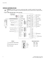
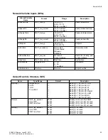
Low Pressure Alarm (LP)
To connect the Low Pressure alarm to the digital input, attach one wire of the contact to LP (T10) and the other wire to
the adjacent common (T9). This must be a dry contact switch.
High Pressure Alarm (HP)
To connect the High Pressure alarm to the digital input, attach one wire of the contact to HP(T8) and the other wire to
the adjacent common (T9). This must be a dry contact switch.
Heat Pump Power Transducer (POW, optional)
To connect the power transducer to the unit, connect the positive wire from the sensor to POW (T11) and the other wire
to the adjacent common (T12). The sensor must be provided and configured by Taco. It is required if the HPU3 needs
to report energy usage to a GHP1 for COP calculations.
Supply Air Humidity (SAH)
To connect a humidity sensor to the unit, connect one wire from the sensor to SAH (T14) and the other wire to the adja-
cent common (T15). This is required when humidifying to prevent saturating the air duct.
Space Temperature / Space Humidity (ST, optional)
To connect a thermistor (Precon III) or a humdity sensor to the analog input, attach one wire of the sensor to ST (T7)
and the other wire to the adjacent common (T6). The thermistor or humidity sensor can be used if no TS300 series
thermostat is being used.
Supply Air Temperature (SAT, optional)
To connect a thermistor (Precon III) to the analog input, attach one wire of the sensor to ST (T13) and the other wire to
the adjacent common (T12).
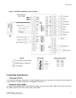
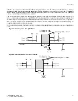
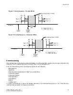
Connecting Output Devices
Stage 1 & Stage 2 (S1, S2)
The outputs for the stages must be connected to 24 VAC pilot relays if the loads are greater than 1 Amp for each pump.
If the loads are less than 1 Amp, connect stage 1 to S1 (T28) and adjacent COM (T27), and connect stage 2 to S2
(T26) and adjacent COM (T27).
Reversing Valve (RV)
The output for the reversing valve must be connected to a 24 VAC pilot relays if the load is greater than 1 Amp. If the
load is less than 1 Amp, connect the reversing valve input to RV (T29) and adjacent COM (T30).
Digital Fan (FAN)
The output for the fan must be connected to a 24 VAC pilot relay if the load is greater than 1 Amp. If the load is less
than 1 Amp, connect the fan input to FAN (T31) and adjacent COM (T30).
Dehumidification (DHUM)
The dehumidification mode output must be connected to a 24 VAC pilot relays if the load is greater than 1 Amp. If the
load is less than 1 Amp, connect the fan input to DHUM (T25) and adjacent COM (T24).
Humidification (HUM)
The humidification output must be connected to a 24 VAC pilot relay if the load is greater than 1 Amp. If the load is less
than 1 Amp, connect the external humidification signal to HUM (T23) and the adjacent COM (T24).
Reheat Valve (RH)
The reheat valve output must be connected to a 24 VAC pilot relay if the load is greater than 1 Amp. If the load is less
than 1 Amp, connect the reheat valve to RH (T22) and the adjacent COM (T21).


