

iWorx® HPU3
505-035, Effective: June 30, 2015
11
© 2015 Taco Electronic Solutions, Inc.
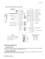
Auxiliary Heat (AUX)
The auxiliary heat output must be connected to a 24 VAC pilot relay if the load is greater than 1 Amp. If the load is less
than 1 Amp, connect the auxiliary heat output to AUX (T20) and the adjacent COM (T21).
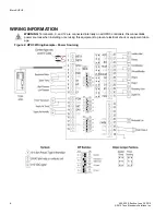
Modulated Fan (FANM)
The modulated fan output can be set to 0-10 V max through the control logic. Connect the positive wire from the fan to
FANM (T37) and the other wire to COM (T36).
Other Connections
Network (LON)
Network wiring must be twisted pair. One network wire must be connected to terminal NETA (T1) and the other network
wire must be connected to terminal NETB (T2). Polarity is not an issue since an FTT-10A network is used for commu-
nications.
Power (PWR)
Connect one output wire from a 24 VAC power supply to PWR (T39) and the other output wire from the power supply to
the adjacent common terminal (T38). T38 must be connected to earth ground.
Ground (GND)
Terminal GND
(T40) must be connected to earth ground. Failure to properly ground this equipment will
result in improper operation. Improper grounding may also increase the risk of electrical shock, and may
increase the possibility of interference with radio and TV reception.
SPECIFICATIONS
Electrical
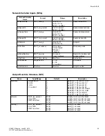
Inputs
• Cabling: twisted shielded pair, 18 AWG recommended—500 feet max. (152 meters)
• Resolution: 10 bit
Stat
• Precon Type III 10K thermistor, or
• 12 Volt nominal, internally limited to 0.04 A (SLink)
Supply Air Temp
• Precon Type III 10K thermistor
Heat Pump Power Transducer
• 0 to 10 Volts DC
Equipment Status, High Pressure Alarm, Low Pressure Alarm
• Dry Contact
• Configurable as Disabled, Normally Open, or Normally Closed
• 5 Volts DC Max
Outputs
Stage 1, Stage 2, Reversing Valve, Fan, and Dehumidification
• 24
Volts
AC


