iWorx® HPU3
14
505-035, Effective: June 30, 2015
© 2015 Taco Electronic Solutions, Inc.
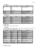
Three digital inputs are provided to monitor the status of the equipment within the unit. An external contact may be
wired to these input to provide additional equipment safety interlocks. When the contact closes, the controller shuts the
unit down. An alarm is reported to the LCI when this condition exists. For more detail on response and recovery to the
digital alarms, see the appropriate sections under “Sequence of Operation.”
The HPU3 can be synchronized to the main plant water supply through its global unit enable feature. The status of the
supply water flow is measured by an external device, and provided to the controller over the network.
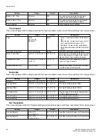
The controller monitors the runtime of the fan. When the runtime exceeds a programmable limit, a maintenance alarm
is reported to the LCI.
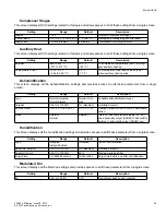
When the space temperature exceeds a programmable limit, a high limit alarm is reported to the LCI. When the space
temperature drops below a programmable limit, a low limit alarm is reported to the LCI. When the space temperature
returns to the proper range, a return to normal alarm is reported to the LCI.
When the zone humidity rises above the humidity setpoint, dehumidification is enabled by activating the dehumidifica-
tion output (external dehumidification), and optionally, the cooling stages (internal dehumidification). Dehumidification
is disabled when zone air humidity drops below the setpoint by 3%.
An analog output is available to modulate a variable speed fan to maintain a consistent Supply Air Temperature. This
output is governed by a P+I loop with a thermistor based sensor to monitor the Supply Air Temperature.
SEQUENCE OF OPERATION
This section describes the detailed sequence of operation for the controller control algorithms.
Setpoints
The heating and cooling setpoint for both occupied and unoccupied periods are programmable values. The space set-
point is a calculated value based on the programmed heating setpoint, cooling setpoint and current operating mode
(i.e. occupied or unoccupied).
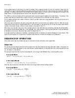
The space setpoint is derived by first calculating the zero energy band (ZEB) for the current operating mode.
Occupied Mode
Unoccupied Mode
Next, the space setpoint is calculated from the zero energy band and the heating setpoint.
Occupied Mode
Unoccupied Mode
ZebOcc
OccupiedCoolSp OccupiedHeatSp
–
=
ZebUnocc
Uno
ccupiedCoolSp
Uno
ccupiedHeatSp
–
=
SpaceSp
OccupiedHeatSp
ZebOcc
2
--------------------
+
=
SpaceSp
UnoccupiedHeatSp
ZebUnocc
2
---------------------------
+
=


