iWorx® HPU3
505-035, Effective: June 30, 2015
21
© 2015 Taco Electronic Solutions, Inc.
Global Unit Enable
The controller can be synchronized to the main plant water supply through its global unit enable feature (located on the
ASM2 controller). The status of the supply water flow is measured by an external device, and provided to the HPU3
over the network. The controller waits in shutdown mode until water flow is detected.
Humidification
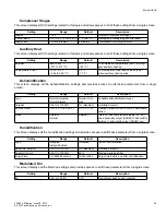
A digital output for humidification (HUM) is provided for adding humidity to the space. When the Space Humidity falls
below the configured
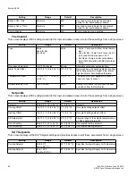
Space RH Setpoint
, the humidification output is energized. Humidification output remains ener-
gized until the Space Humidity rises three percent above the configured setpoint. Humidification may be configured to
operate when Occupied or Always.
If the humidity in the supply duct rises above the configurable
Supply RH Limit
, humidification output is deenergized
regardless of the space humidification requirements.
The fan is used to purge the supply duct before and after the humidification output is energized for a configurable
amount of time.
To enable humidification, sensors for Supply Air Humidity (SAH) and Space Humidity must be present. Space Humidity
may be obtained from an SLink thermostat, or alternatively, from a separate humidity sensor connected to the STAT
input (such as when temperature is provided from a BZU3 thermostat that does not provide humidity - see "Hydronic
Zone Interaction"). The STAT input is configured in the
Thermostat
configuration screen.
To disable humidification, configure either
Space RH Setpoint
or
Supply RH Limit
to zero percent. If either (or both) of
these are configured to zero percent, humidification is not enabled.
Thermostat
Space temperature, current humidity, setpoint adjustment, fan auto/on status (depending on the thermostat model),
and occupancy override request are monitored by the thermostat and sent to the controller.
The controller automatically detects a failure of the thermostat. When the thermostat fails, the compressor stages turn
off, the fan turns off, and control is disabled.
Note:
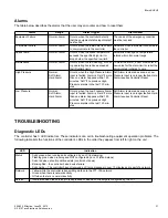
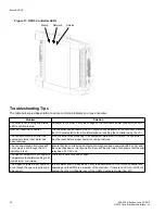
The thermostat must be connected. The status LED on the controller turns solid red if the thermostat is not con-
nected. Once the thermostat is connected, the status LED turns green indicating normal operation. Alternatively, the
thermostat input (STAT) may be used for an RH sensor for Space Humidity, if the controller is also configured as part of
a hydronic zone - see "Hydronic Zone Interaction".
Local Backup Schedule
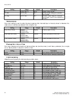
The LCI normally determines the operating mode. A local backup schedule can be defined for situations when the LCI
is not available. When the controller detects that the LCI is not available (after 10 minutes without communication), it
resorts to the configured local backup schedule. If the local backup schedule is disabled, the controller defaults to occu-
pied mode.
The configured occupied and unoccupied times are used in determining the current operating mode of the controller
when it is running the backup schedule. By default, both the unoccupied and occupied time are set to zero, which dis-
ables the local backup schedule. This causes the controller to default to the occupied mode of operation if it cannot
communicate with the LCI.
Runtime Accumulation
The total runtime is accumulated for the compressor and fan outputs. The runtimes can be used to indicate that main-
tenance is required on the equipment controlled by these outputs. The runtime can be reset by an operator or mainte-
nance person once servicing has been performed.

