iWorx® HPU3
22
505-035, Effective: June 30, 2015
© 2015 Taco Electronic Solutions, Inc.
Reversing Valve
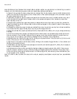
The reversing valve action can be set to “Energize on Heat” or “Energize on Cool.” The reversing valve default setting
is to “Energize on Heat.” This setting can be changed in the All Settings configuration area.
Supply Air Temperature Fan Modulated Output
The calculated Supply Air Temperature (SAT) Setpoint is dependent on whether the HPU3 is in heating or cooling oper-
ation. When the HPU3 is in heating mode, the SAT setpoint is the SAT heating setpoint. When the HPU3 is in cooling
mode, the SAT setpoint is the SAT cooling setpoint. If present, the SAT output is active whenever the Heat Pump Fan
is energized. The output is modulated by a P+I control loop based on the SAT setpoint and the SAT input. The P+I con-
trol loop modulates the output to maintain a constant SAT.
When the HPU3 is in cooling mode, as the SAT increases above the SAT setpoint, the SAT output is modulated higher.
The SAT output is modulated lower as the temperature decreases below the SAT setpoint.
When the HPU3 is in heating mode, as the SAT decreases below the SAT setpoint, the SAT output is modulated
higher. The SAT output is modulated higher as the temperature increases above the SAT setpoint.
Alarms and Events
The controller will detect certain alarm conditions and send them to the LCI. Before this can occur, the user must use
the LCI to configure the controller.
Pressure Alarms
High and low pressure alarm inputs are monitored to determine if a pressure alarm condition exists in the heat pump.
The pressure alarms may be configured for normally open (active when shorted to ground) or normally closed (active
when open).
When a pressure alarm input becomes active, a (high or low) pressure alarm message is sent to the LCI and the heat
pump outputs are disabled. When the pressure alarm clears, normal heat pump output is resumed.
If the pressure alarm input becomes active again within two hours, or if the pressure alarm remains active for two hours
without clearing, all the controller's outputs are disabled and the controller's status LED turns red. A hard reset is
required before the controller resumes operation again.
Thermostat Failure
The controller automatically detects the presence of the local thermostat and monitors its status. If the thermostat fails
to communicate with the controller, a Thermostat Failed Alarm is generated and the controller’s status LED turns red.
Maintenance Alarm
The controller provides programmable run limits for generating a runtime Maintenance Alarm. When any of the cooling,
heating, or fan runtime limits are exceeded, a maintenance alarm is sent to the LCI.
Space Temperature Alarms
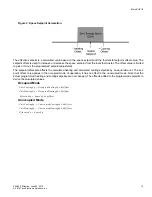
The controller generates high and low limit alarms for the space temperature. The user can configure a programmable
space temperature alarm limit offset. The temperature limits are calculated based on the control setpoints, alarm limit
offset, and control band.
When the measured space temperature exceeds the high limit, a high limit alarm (Space Temperature High Limit
Alarm) is generated. When the space temperature drops below the low limit, a low limit alarm is generated (Space
Temperature Low Limit Alarm). A return to normal alarm is generated when the space temperature is between the high
and low limit (Space Temperature Return to Normal).
To help eliminate nuisance alarms when the controller switches between the unoccupied and occupied modes of oper-
ation, space temperature alarms are not reported for 30 minutes following the switch.

