- 4 -
6 - Pump Installation
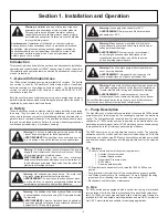
The 1900e series pump is protected with a double box during shipping.
It can be lifted from the box by the heat sink.
Warning:
Pump may be heavy.
Provide yourself help if needed.
Warning:
The majority of mechanical seal failures are due
to poor media (fluid) quality in the system. To maximize
seal life, media quality must be maintained in the system,
and TDS (Total Dissoled Solids)/TSS (Total Suspended
Solids) should not exceed 500ppm with standard carbon/
Silicon-Carbide seals. The use of inhibitor based glycols is acceptable,
but additional inhibitors should not be added. Always follow the glycol
manufacturer's specification for system preparation and water quality.
Treatment with silicates should not be used. Failure to maintain media
quality will void the standard Taco warranty.
AVERTISSEMENT:
La plupart des défaillances des garnitures
mécaniques sont dues à une mauvaise qualité de caloporteur. Pour
prolonger la durée des joints, on doit maintenir la qualité du fluide dans
le système et les solides dissouts totaux (SDT)/matières en suspension
totales (MES) ne doivent pas dépasser 500 ppm avec des joints stan-
dard en carbone/carbure de silicium. L'utilisation de glycols/inhibiteurs
combinés est acceptable, mais on ne doit y ajouter aucun inhibiteur
supplémentaire. Suivez toujours les spécifications du fabricant du
glycol pour la préparation du système et la qualité du fluide. On ne doit
pas utiliser de traitement aux silicates. Ne pas maintenir la qualité du
fluide annulera la garantie standard de Taco.
AVERTISSEMENT:
La pompe est lourde.
Veillez à demander de l’aide si nécessaire.
It is recommended that the1900e series pumps be installed with at least 5 to
10 pipe diameters of straight pipe on the inlet and outlet of the pump. Use all
nuts and bolts to attach companion flanges to the pump flanges.
The 1915ecm uses a mechanical seal. To ensure reliability of the seal, a
minimum continuous safe flow rate of 9 gpm at full load (15% of BEP flow)
is recommended. Ensure flange bolts are adequately torqued.
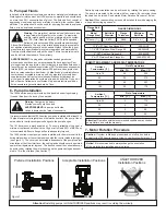
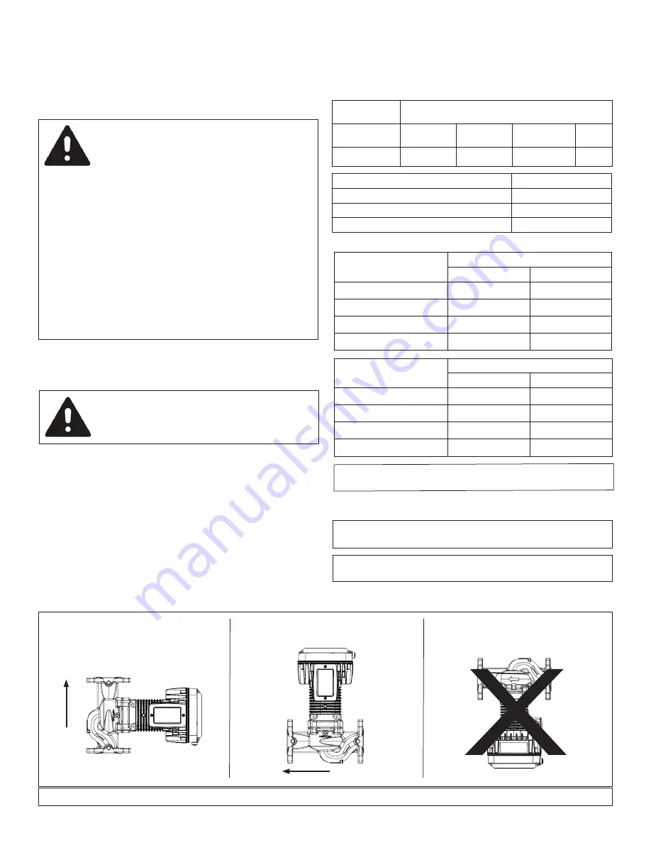
The 1900e series model pumps can be installed with the motor shaft in the
horizontal position or the vertical position with the control module facing up
(see Figure 1). The cover can be rotated independent of the pump to adjust
orientation of the User Interface – the cable glands should never be pointed
upward to mitigate water ingress. The desired conduit box orientation can
be achieved by rotating the motor housing on the pump casing and assem-
bled to 10 in-lbs of torque (See Section 7).
Caution:
When reassembling, care should be taken to avoid damaging the
o-ring and insuring a good seal.
Figure 1.
Preferred Installation Positions
Acceptable Installation Positions
UNAUTHORIZED
Installation Positions
Attention!
Installing pumps in UNAUTHORIZED positions may result in voiding the warranty.
Flange Bolt
Size
FLANGE DIMENSIONS
Model
(Flange Size)
Bolt Hole
Diameter
Flange
Thickness
Minimum
Bolt Size
Qty.
1915ecm (1
1
/
2
”)
0.672
0.688
5/8” x 2
1
/
4
”
2
PERMITTED AMBIENT AND MEDIA TEMPERATURE
Ambient
Temperature [°F]
Fluid Temperature
Min. [°F]
Max. [°F]
Up to 75
36
230
85
36
212
95
36
203
105
36
175
Ambient
Temperature [°C]
Fluid Temperature
Min. [°C]
Max. [°C]
Up to 25
2
110
30
2
100
35
2
90
40
2
80
Attention!
Operation outside recommended conditions may shorten
pump lifetime and void the warranty.
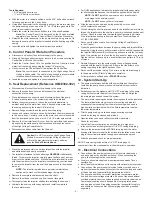
7 - Motor Rotation Procedure
Caution:
If system is filled and pressurized, shut off valves before
and after the 1900e series pump. Allow to cool if system fluid is hot.
Notice!
It is recommended to always change the orientation
of the motor before installing pump in piping.
5 - Pumped Fluids
In hot and chilled hydronic systems, use water or water/glycol mixtures only.
Water/glycol mixtures must be HVAC-system compatible and should have
no more than 50% concentration of glycol. The fluid shall not consist of
aggressive or explosive additives, mixtures of mineral oils or solid or fibrous
particles. The pump should not be used for pumping flammable, explosive
fluids, or in an explosive environment.
Desired pump orientation can be achieved by rotating the pump casing.
The pump is mounted to the volute with four screws. By removing those
the head can be turned. See detailed Motor Rotation Procedure 7 below.
1-1/2" NPT Cast Iron Flange Kit
1600-031RP
1-1/2" NPT Stainless Steel Flange Kit
198-3084RP
2" NPT Cast Iron Flange Kit
1600-032RP
2" NPT Stainless Steel Flange Kit
1600-032SRP
FLOW
FLOW


