
- 5 -
8 - Control Panel UI Rotation Procedure
a. Disconnect and lockout the electrical supply to the pump.
b. Using a #2 philips head screwdriver, remove the 4 screws securing the
Control Panel UI to the Control Box.
c. Rotate the Control Panel UI to the position desired. If desired, drain
water from the casing body using the lowest 1/8" drain plug.
d. Gently remove the Control Panel UI away from the Control Box.
Note:
The control panel is connected to the High Voltage Power
Unit by a ribbon cable. The cable is long enough to accommodate
rotation without disconnecting the cable from the UI.
e. Insert the screws and tighten in a crisscross pattern.
9 - Seal Replacement (Reference IOM #302-392)
a. Disconnect and lockout the electrical supply to the pump.
b. Remove the conduit box cover and disconnect the electrical
connections to the pump.
c. Close isolation valves on suction and discharge sides of the pump.
If valves are not present, the system may need to be drained.
d. Relieve the system pressure, reduce the system temperature to
ambient and drain the water from body. If desired, drain water from
the casing body using the lowest 1/8" drain plug.
e. Remove flange nuts/bolts and the pump from the piping.
f. Loosen and remove the four body bolts that attach the motor assembly
to the pump body. Carefully remove the motor and control assembly
from the pump body at any one of six 0.3' x 0.15' water egress slots.
g. Remove the User Interface (UI) cover from the motor/heat sink assem-
bly exposing the slotted pump shaft access port through the center
of the High Voltage Power Module.
h. Disconnect the ribbon cable from the UI panel.
i. Place the motor assembly in a horizontal position with the impeller
and slotted shaft end easily accessible.
j. The impeller is fastened to the shaft using a
REVERSE
(Left-Handed)
thread. To remove the impeller, carefully place the flat end of a screw-
driver into the slotted shaft end. While holding the rotor/shaft in place
with the screwdriver, turn the impeller clockwise using your free hand
to remove the impeller from the shaft and gain access to the mechan-
ical seal.
NOTE:
The impeller is made from a polymeric material, use
caution not to crack or otherwise damage the impeller.
k. Remove the complete seal assembly from the shaft.
l. Remove the old seal seat and cup from the seal face plate.
m. Thoroughly clean the impeller shaft before installing the new seal.
n. Lubricate the new cup with soapy water and install new parts in
the face plate recess.
o. For DHW applications, lubricate the impeller shaft with soapy water,
for all other applications use the lubricant supplied with the seal kit.
NOTE:
Do
NOT
install the new seal on a dry impeller shaft
or damage to the seal may result.
NOTE:
Do
NOT
use any other oil or grease.
p. Slide the new carbon seal and spring assembly onto the shaft
until it contacts the seal seat.
q. While holding the shaft in place as used in the impeller removal steps,
thread the impeller onto the shaft in a counter-clockwise direction until
it stops. Check to make sure the impeller/shaft assembly will rotate.
If the impeller does not spin freely, contact Taco Technical Support
at 1 (401) 942-8000.
r. Reconnect the ribbon cable from the High Voltage Power Module
to the UI panel.
s. Clean the gasket surfaces between the pump casing and Impeller/Motor
assembly. Using the new gasket provided with the seal kit, reassemble
the Impeller/Motor assembly to the casing and secure with the four body
bolts. Use caution not to pinch the body gasket or leaks may result.
Tighten the four bolts evenly in a double crisscross pattern to 70 in-lb.
of torque.
t. Reinstall the pump into the system using the new flange gaskets
supplied with the seal kit if required. Be sure that the arrow on the
casing is pointing in the right direction of flow.
u. Reconnect the electrical wiring. Do not turn on the electrical supply
to the pump until all “Start-Up” steps are complete.
v. Follow procedure outlined under
START-UP
section.
10 - System Start-Up
a. The pump must always be filled with system fluid and the system
vented as the pump uses a mechanical seal which requires fluid
lubrication.
b. Partially unscrew the highest point 1/8” NPT drain plug in the pump
casing until only water trickles from the screw threads. Retighten
the drain plug as needed to seal the system.
c. The motor stator openings and stator housing should not be insulated.
The thermal insulation may prevent motor cooling and prohibit
condensate from escaping from the motor housing when used in
high humidity environments where the fluid temperature is below
the motor temperature.
d. Prior to pump start-up, closed heating and cooling systems
should be thoroughly cleaned and drained.
e. Open isolation valves and refill system with clean water.
Check for any leaks.
f. Vent all air from system at an air vent located at a high point
in the system and at the highest point 1/8" NPT casing drain plug.
g. Remove the lowest point black EPDM drain plug from the motor
housing with the motor shaft in the horizontal orientation or any drain
plug in the vertical orientation to support condensation egress.
h. Start the pump and check for proper operation.
11 - Electrical Connections
a. Connection of the pump must comply with local electrical codes
and be carried out by qualified personnel. When connecting the
pump, the following must be considered:
b. Local or national electrical code requirements supersede Taco’s
specification.
c. Install an electrical disconnect to comply with national electrical code.
d. Connection of the power supply electrical cable must be done in a
manner that ensures it does not contact the motor housing and volute
of the device, due to potential high temperatures of both.
e. The pump has built-in over current protection, temperature protec-
tion, and basic overvoltage protection. It does not require additional
overload protection devices unless required by local electrical codes.
Power supply cabling should be capable of carrying rated power
and be properly fused. Grounding connection is essential for safety
and should be connected first. System piping should be grounded
separately.
Tools Required:
• 3/16” ball-end hex wrench
• ¼” or 3/8” flat tip screw driver
a. With the motor in a vertical position, use the 3/16” ball-end hex wrench
to loosen and remove the 4 body bolts.
b. Using a flat tip screwdriver if necessary, gently pry the motor away from
the pump housing at any one of six 0.3' x 0.15' water egress slots. The
motor is now ready to be rotated.
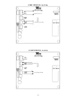
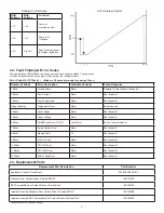
c. Rotate the motor so that the conduit box is in the desired position.
Note:
The Control Panel UI is designed so that it can be rotated
separately. (see Section 8 Control Panel UI Rotation Procedure)
d. Reinstall the motor assembly to the pump housing being sure not to
damage the seal and the impeller is inserted into the floating ring of the
casing.
e. Insert the bolts and tighten in a double crisscross pattern.
Caution:
Do NOT remove the High Voltage Power
Module. Removal of the High Voltage Power Unit
will void the manufacturer’s warranty and may
pose the
Risk of Electric Shock
.
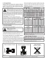
a. NOTE: Pump casing includes three 1/8" NPT drain plugs to
evacuate air from the mechanical seal chamber prior to operation.


