

- 6 -
12 - Setup and Operation
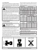
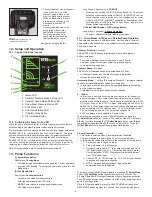
12.1 - Control (UI) Panel Layout
0-10V
Lead/2-Pump Operation
Proportional Pressure
Status
SELECT
MODE
SET
MODE
2-PUMP
OPERATION
HOLD BOTH 3s
000-0000
1915
ecm
HIGH-EFFICIENCY CIRCULATOR
TM
25
35
45
65
HEAD FEE
T
HEAD FEE
T
FLOW GPM — Constant Pressure
120
15
25
35
FLOW GPM — Constant Speed
80 100 120
MODES
1
2
3
4
5
6
7
8
1. Status LED
2. Constant Pressure Mode Setting LED
3. Constant Speed Mode Setting LED
4. Proportional Pressure Mode LED
5. 0-10v Mode LED
6. 2-Pump Operation LED
7. [^] Select Mode Button
8. [O] Set Mode Button
12.2 - Switching the Pump On and Off
When the pump is powered for the first time, it operates with the factory
default setting in Constant Pressure mode equal to 33ft of head.
The pump requires dry contact to run and comes with a jumper across the
ENABLE INPUT (J4) contacts found on the Control Panel UI. The pump
will run when connected to a power source when the jumper is connected.
Turning the pump on/off remotely is accomplished by accessing the
ENABLE INPUT (J4) contacts on the UI control board located under the
UI and connecting the contacts to an external relay. Access is gained by
removing the 4 screws located in each of the UI panel’s four corners.
Note: After powering up, wait 5 minutes before powering off.
13 - Pump Functions
[^] Select Mode Button
Short press:
Change Mode
• Scrolling through operational modes upwards. Current operation-
al mode LED blinking. To accept the new mode press the Set
Mode button.
Long Press (10 seconds) –
LOCKOUT
• Pressing and holding the [O] Set Mode Button for 10 seconds
activates or deactivates pump LOCKOUT. In LOCKOUT, the cur-
rently selected mode is active only. No changes can be made
while in LOCKOUT. LOCKOUT activation or deactivation is ac-
knowledged by all LED’s blinking on and off once, and returns to
display current operating mode.
[^] Select Mode [O] Set Mode Button
Long press (3 seconds):
2-Pump Operation
• To select or deselect 2-pump (lead/lag) operation.
13.1 - Pump Modes, 0-10Vdc and Parallel Pump Operation
The pump can operate in 9 different modes. Set the pump in the most
appropriate mode depending on the system where the pump operates.
The pump modes are:
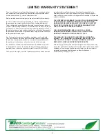
Constant Pressure:
4 settings
65ft, 45ft, 35ft, 25ft (Changes impeller speed to maintain pressure
as flow increases)
• The pump maintains the selected pressure from 0 flow to
maximum power. At maximum power the pressure begins
to drop with increasing flow.
Constant Speed:
3
settings
35ft, 25ft, 15ft (Maintains speed at selected head at 0 flow)
• In Constant Speed mode the impeller speed is maintained
through the entire range of flow.
Automatic Mode:
1 setting (Proportional Pressure - increases impeller
speed to increase differential head as flow increases)
• In automatic mode the pump sets the operating pressure depending
on the system resistance.
• The parameters are preset and cannot be changed.
0 – 10Vdc:
• In this mode, all automatic curves are deactivated for full control via
an external signal. A dry contact from the external source is used to
activate or deactivate the pump. Pump speed is controlled via a 0-10V
DC signal. Loss of the 0-10V DC signal defaults pump to 50% of full
speed. The 0-10Vdc output signal is a linear relationship between speed
and Vdc regardless of the selected mode. 1-3 Vdc is minimum speed,
10 Vdc is maximum speed, 6.5 Vdc is medium speed etc.
• 0-10Vdc operation is unavailable in 2 pump mode.
To switch between modes (except 2-Pump Operation) depress the
[^] Select Mode
button for 1 second. The selected mode LED will begin
blinking. Continue pressing the
[^] Select Mode
button to scroll through
the available modes indicated by the mode’s blinking LED. Press the
[O] Set Mode
button to accept the desired operating mode.
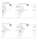
2-Pump Operation:
1 setting
• This option is selected when 2-pump alternation is desired.
• Pumps will alternate run-time every 24 hours (not adjustable).
• In this mode the lead pump will control the operation of the lag pump.
1. Set both pumps to the same Mode
2. Turn main power off to both pumps
3. Connect Primary Pump “P1” relay output common and NC to
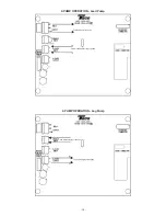
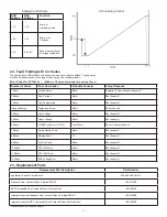
“P2” Enable Input (see 21.1 - Connection Examples Parallel
Pump Operation). NOTE: Remove factory installed jumper
from “P2” Enable Input
4. Connect “P2” 0 – 10Vdc Output to “P1” 0-10Vdc Input, positive
to positive and negative to negative
5. NOTE: Between pumps standard 18ga unshielded
communication wire is sufficient
To activate or deactivate 2-Pump Operation, press the
[^] Select Mode
button
+ [O] Set Mode
button together and hold for 3 seconds. The
2-Pump Operation LED will light indicating 2-Pump Operation activation.
The LED will go out upon deactivation. Only the master pump should be
set to 2-pump operation.
Once in 2-Pump operation, press the SELECT MODE button and the
SEST MODE button together for 1 second to switch the running pump.
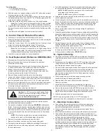
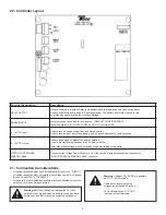
f. Connect the black wire of the pump
to the “Hot/ Live” wire of the
system. Typically black, or red
wire if no black wire is present.
When no black wire is present,
a red wire is a secondary live
wire found in some 220/1
circuits.
Connect the white wire of the
pump to the white or gray
neutral wire of the system.
The green ground wire is
connected to the grounding
terminal inside the pump.
See figure 2 noted to the left.
Figure 2
1915ecm
Electrical opening: 1/2”
14 MPSM standard thread
[O] Set Mode Button
Short press:
Confirm Selection
• To confirm the mode currently selected.
Selected operational mode LED solid.
NOTE:
Pump returns to previous operational mode
if Set Mode is not pressed.


