
- 7 -
14 - Specification
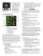
14.1 - Application
• Maximum Operating Pressure: 175 PSI (12 bar)
• Water Temperature Range: 36
°
– 230
°
F (2.2
°
– 110
°
C)
• Ambient Operation Temperature Range: 32
°
– 104
°
F (0
°
– 40
°
C)
• Relative Humidity: Max. 95% non-condensing
• Central heating application is designed for closed loop heating and cool-
ing systems pumping water or a water/glycol mixture.
• DHW application is designed for open loop potable water systems.
Rated NSF/ANSI 61 & 372 Commercial Hot (180 °F)
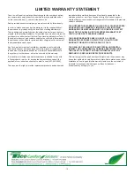
• NPSHr - Minimum static inlet pressure at pump suction to avoid
cavitation and mechanical seal damage:
Note:
Supply voltages below 230V may result in performance
reduction at low flow. — For 1915ecm only.
Note:
This equipment has been tested and found to comply with the limits
for a Class A digital device, pursuant to part 15 of the FCC Rules. These
limits are designed to provide reasonable protection against harmful
interference in a residential installation. This equipment generates, uses
and can radiate radio frequency energy and, if not installed and used in
accordance with the instructions, may cause harmful interference to radio
communications. However, there is no guarantee that interference will
not occur in a particular installation. If this equipment does cause harmful
interference to radio or television reception, which can be determined by
turning the equipment off and on, the user is encouraged to try to correct
the interference by one or more of the following measures:
•
Reorient or relocate the receiving antenna.
•
Increase the separation between the equipment and receiver.
•
Connect the equipment into an outlet on a circuit different from that
to which the receiver is connected.
•
Consult the dealer or an experienced radio/TV technician for help.
Fluid Temperatures
PSI / bar
112°F (50°C)
5.1 / 0.4
176°F (80°C)
10.4 / 0.8
230°F (110°C)
23.7 / 1.7
14.2 - For indoor use only - employer uniquement a l’interieur.
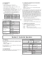
15 - Electrical Ratings
Description
1915ecm (G1)
Pump Ratings
1 phase
200-240V, 47-63Hz
Power Consumption (HP) 0.027-0.87 HP
Power Consumption (W)
20-650W
Rated Current
(1 phase, 200-240V)
0.25-3.3A
Relay Output
30 VDC Max.
Load up to 2A
24VAC Max.
Load up to 3A
Analog Input
Input Voltage: 0-10V, 10mA
Output Voltage: 0-10V, 10mA
16 - Standards, Protection and Connection
• Insulation: Class H (180
°
C)
• Enclosure: Type 2
• Integrated Motor Protection (Electronically Protected)
• Continuous Duty
• UL778
• CAN/CSAC22.2#108, #100, #107.1, EMC (89/366EEC):EN61000
• Flange Connections: 2-bolt
17 - Materials of Construction
• Casing
• Impeller
• Shaft
• Bearing
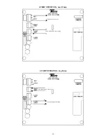
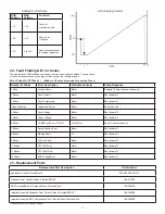
Section 2. Controller Operation
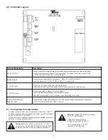
18 - Features
This section describes the controller features for 1900e series of pumps.
The controller is used for various remote control applications, including:
• Remote on/off
• Analog 0 - 10 V voltage control
• Status relay feedback
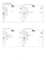
There are several possible connection configurations. Not all functions can
be used simultaneously.
• on/off + 0 - 10 V + relay output
19 - Specifications
Tables to the right provide an overview of Controller specifications. For de-
tails, please refer to appropriate sections of this manual.
General Data
Ambient Humidity
< 95% relative,
non-condensing
Also see appropriate pump
data for other ambient
specifications.
Analog Signals
Input Voltage Range
0 to 10V DC
When used as input. 10 mA
max. drive required.
15 VDC Max.
Output Voltage Range
0 to 10V DC When used as output. 10 mA
max. load allowed.
Input Resistance
~3 kΩ
Relay Specifications
Connection Type
Terminal Block
Rating
24V AC, 3A
30V DC, 2A
HVAC application
: Ductile Iron, Cataphoresis Coated
DHW application
: Stainless Steel
PPS
Stainless Steel 6202 Series Drive End
Sealed for Life Ball Bearings, 6002 Series Non-Drive End


