102-434
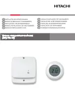
Room Thermostat (Digital) Model 568-22
Instruction Sheet
SUPERSEDES: New
EFFECTIVE:
December 1
7
, 2015
Plant ID# 001-4108
Installation:
The thermostat should be installed approximately 5 feet above the
floor and where the temperature is constant and good air circulation.
Do not mount thermostat on outside walls, other cold walls, near
entrance doors, draft locations or near hot or cold registers.
Mounting:
Remove front cover by inserting small screw driver in side slot
between cover and tab, then pry cover off as shown in figure 2.
Route wires through hole in base and mount thermostat to wall using
two screws.
Wiring:
Connect the “R” wire to the “COM” terminal on thermostat as shown in figure 3.
Connect the “W” wire to “NO” terminal on thermostat as shown in figure 3.
Installing Batteries:
Install the 2 AAA batteries in slide out battery holder as shown in figure 1. The thermostat
can detect when the batteries are getting weak, a low-battery indicator shows in the
display.
Operation:
To adjust room temperature settings, press the UP or Down buttons to select the
desired room temperature and the icon will appear. After 8 seconds the icon will
disappear and return to show the actual room temperature. When the thermostat is calling for heat,
the thermometer icon will blink.
Specifications:
Electrical Data
Power Supply – 3 VDC, 2@AAA Batteries
Switch Rating – 24 VAC 1.0 Amps
Switch Action – Relay Action (Dry Contacts)
Thermal Data
Temperature Range – 40°F to 95°F
Operating Temperature – - 32°F to 104°F
Storage Temperature – - 32°F to 122°F
Operating Humidity Range – 0 to 90% noncondensing
WARNING: To prevent electric shock and/or
equipment damage, disconnect electrical power
to the system at the main fuse or circuit breaker
until installation is complete.
Figure 2.0
Figure 2.1
Figure 2.2


