background image

13


TESTING THE SENSORS

Do not apply voltage to the sensor or to the sensor input of the control as this will result in damage

to either the sensor, the control, or both the sensor and the control.

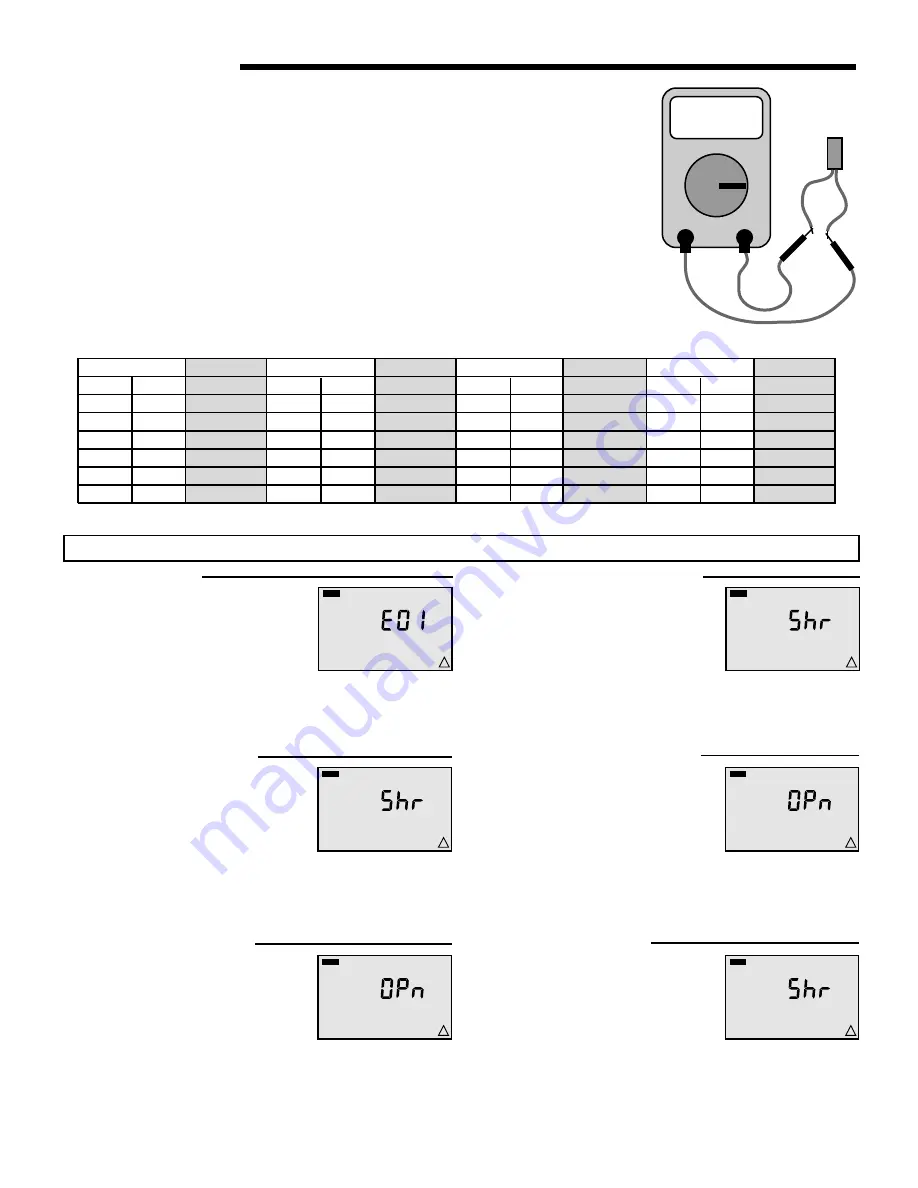
A quality testing meter capable of measuring up to 2,000,000 ohms and a good quality digital

thermometer are required to test the sensors. If a digital thermometer is not available, place a

second sensor next to the original sensor and compare the readings.

Begin by measuring the temperature at the sensor location using the digital thermometer. Next,

measure the resistance of the sensor using the testing meter. Ensure that the sensor is discon-

nect from the control at the time of testing. Using the reference chart below, determine the sensor’s

temperature. Compare the sensor’s temperature to that measured by the digital thermometer. The

two temperature readings should be close.

If the sensors temperature is too high, this can indicate that there is a partial short in the sensor

wiring. If the sensor’s temperature is too low, this can indicate that there is a loose connection or

break in the sensor wiring. Isolate and repair the problem. If the problem is isolated to the sensor,

replace the sensor.


-30

-20

-10

0

10

20

30

40

50

60

70

80

90

100

110

120

130

140

150

160

170

180

190

200

-34

-29

-23

-18

-12

-7

-1

4

10

16

21

27

32

38

43

49

54

60

66

71

77

82

88

93

234,000

165,000

118,000

85,500

62,500

46,000

34,500

26,000

20,000

15,500

12,000

9,300

7,300

5,800

4,700

3,800

3,100

2,500

2,000

1,700

1,400

1,200

1,000

800

Temperature Resistance

F

C

Ohms

Temperature Resistance

F

C

Ohms

Temperature Resistance

F

C

Ohms

Temperature Resistance

F

C

Ohms


EEPROM Read Error

The control was unable to read the in-

stallers settings from its memory. The

control was forced to load the factory

defaults for all settings. The control will

stop operation until all of the settings

in the Adjust menu have been checked.

O


Error Messages

VIEW

!

MIX

VIEW

!

RET


Mixing Return Sensor Short Circuit

A short circuit has been detected in the

mixing return sensor. If the Maximum

Delta T setting is set to OFF, the con-

trol  continues  operation.  If  the  Maxi-

mum Delta T setting is not set to OFF,

the  control  stops  operation  until  the

fault  is  corrected. To  clear  this  error

message, correct the short circuit and

press any button on the control.

M


Outdoor Sensor Short Circuit

A short circuit has been detected in the

outdoor sensor. The control assumes

an outdoor temperature of 32

°

F (0

°

C)

and continues operation. To clear this

error message, correct the short circuit

and press any button on the control.


OUT

VIEW

!

MIX

VIEW

!

RET


Mixing Return Sensor Open Circuit

An open circuit has been detected in

the mixing return sensor. If the Maxi-

mum Delta T setting is set to OFF, the

control continues operation. If the Maxi-

mum Delta T setting is not set to OFF,

the  control  stops  operation  until  the

fault  is  corrected. To  clear  this  error

message, correct the open circuit and

press any button on the control.

B


Outdoor Sensor Open Circuit

An open circuit has been detected in

the  outdoor  sensor.  The  control  as-

sumes an outdoor temperature of 32

°

F

(0

°

C) and continues operation. To clear

this error message, correct the open

circuit and press any button on the con-

trol.


OUT

VIEW

!

VIEW

!

BOIL


Boiler Sensor Short Circuit

A short circuit has been detected in the

boiler  sensor.  The  boiler  contact  is

operated  as  if  a  boiler  sensor  is  not

installed. The control provides a boiler

enable and does not provide boiler pro-

tection. To  clear  this  error  message,

correct the short circuit and press any

button on the control.


Summary of Contents for Radiant Mixing Block

Page 1: ...CEDURE 3 INSTALLATION OF RADIANT MIXING BLOCK 4 OUTDOOR RESET MODE 5 OUTDOOR RESET SETTINGS 5 SETPOINT AND DELTA T MODE 6 SETPOINT AND DELTA T SETTINGS 7 BOILER OPERATION MODE 7 SET UP OF RADIANT MIXING CONTROL 8 DISPLAY OPERATION 11 TROUBLE SHOOTING 13 ERROR MESSAGES 14 REPLACING CARTRIDGE ASSEMBLY 14 REPLACING THE CHECK VALVE 15 TECHNICAL DATA 15 CLEANING 16 LIMITED WARRANTY STATEMENT 16 Plant I...

Page 2: ...2 Typical Piping ...

Page 3: ...a complete injection mixing system Integral to the unit is a variable speed injection circulator constant speed system circulator air elimination and the electronics to drive it all With only four piping connections needed the RMB greatly reduces the time and space required for installation The RMB can be set up to operate as an outdoor reset control a setpoint control or a delta T limiting contro...

Page 4: ...lock Ensure that a proper isolation valve is installed 2 Using proper piping practices connect the return from the radiant heating system to the Radiant Return top right hand connection as indicated on the plastic cover of the Radiant Mixing Block Ensure that a proper isolation valve is installed 3 Using proper piping practices connect the supply from the boiler loop to the Boiler Supply top left ...

Page 5: ...cribed in the Boiler Operation section The RMC also provides boiler protection as described in the Boiler Operation section DEMAND The RMC requires a demand signal before it will begin operation The RMC can use either a powered or an unpowered demand signal Once a demand signal is received the RMC displays the demand pointer in the display and operates as described above Powered Demand The RMC rec...

Page 6: ...rotection as described in the Boiler Operation section DEMAND The RMC requires a demand signal before it will begin operation The RMC can use either a powered or an unpowered demand signal Once a demand signal is received the RMC displays the demand pointer in the display and operates as described above Powered Demand The RMC recognizes a Powered Demand Signal when 24 V ac is applied across the Co...

Page 7: ...he boiler BOILER CONTROL When the RMC controls the boiler the RMC opens and closes the boiler contact in order to control the temperature of the boiler supply water temperature When the RMC is controlling the boiler temperature the RMC will determine the boiler supply water temperature that is required to satisfy the demands of the system The RMC will also determine a differential that is sufficie...

Page 8: ... back off the variable speed injection pump when the boiler temperature drops 1 2 of the Differential below the Boiler Minimum Setting Note If a boiler sensor is not installed the RMC cannot provide boiler protection C CAUTION Improper installation and operation of this product could result in damage to the equipment and possibly personal injury It is your responsibility to ensure that this produc...

Page 9: ...tor from the Radiant Mixing Block to the matching three pin molex connector labelled Var on the back of the RMC circuit board Wiring the Radiant Mixing Block System Pump Connect the system pump s four pin molex connector from the Radiant Mixing Block to the matching four pin molex connector labelled Sys on the back of the RMC circuit board Sys H Pmp Use copper conductors only Power 120 V 10 50 60 ...

Page 10: ...to the eight 8 pin terminal header on the RMC circuit board Press firmly until it snaps into place Insert the two 2 pin plug in terminal block into the two 2 pin terminal header on the RMC circuit board Press firmly until it snaps into place STEP FIVE MOUNTING THE RMC Begin by pushing all excesses wiring back into the Radiant Mixing Block Place the RMC into the Radiant Mixing Block s plastic enclo...

Page 11: ...BOIL DEM VIEW F 1 MIX ADJUST F TARG Delta T Maximum The Delta T Maximum sets the maximum temperature difference between the mixing return sensor and the mixing supply sensor This item is only available if Outdoor Design setting is set to OFF If a mixing return sensor is not installed set this item to OFF Outdoor Design Temperature The Outdoor Design Temperature is the outdoor temperature used in t...

Page 12: ...reased from 0 to 100 over 10 seconds Step Two The variable speed output is decreased from 100 to 0 over 10 seconds Step Three The System Pump is turned on for 10 seconds Step Four The Boiler Contact is turned on After 10 seconds the Boiler Contact and the System Pump contact are turned off The RMC continues normal operation MANUAL OVERRIDE In the event that the RMC fails to operate a manual operat...

Page 13: ...e to read the in stallers settings from its memory The control was forced to load the factory defaults for all settings The control will stop operation until all of the settings in the Adjust menu have been checked O Error Messages VIEW MIX VIEW RET Mixing Return Sensor Short Circuit A short circuit has been detected in the mixing return sensor If the Maximum Delta T setting is set to OFF the con ...

Page 14: ...ss any button on the control MIX VIEW SUP MIX VIEW SUP VIEW BOIL Boiler Sensor Open Circuit An open circuit has been detected in the boiler sensor The boiler contact is operated as if a boiler sensor is not installed The control provides a boiler enable and does not provide boiler pro tection To clear this error message correct the open circuit and press any button on the control If the sensor was...

Page 15: ...rtridge corresponds to the full circulator product number A complete parts list is available from your local plumbing supply wholesaler 7 Reassemble the circulator using the new gasket and bolts supplied 8 Follow the Installation procedure to start up the circulator 1 Disconnect the electrical supply 2 Reduce system pressure to 0 psi and allow system to return to room temperature Isolate the Radia...

Page 16: ...cation the addition of petroleum based fluids or certain chemical additives to the systems or other abuse will not be covered by this warranty If in doubt as to whether a particular substance is suitable for use with a Taco product or part or for any application restrictions consult the applicable Taco instruction sheets or contact Taco at 401 942 8000 Taco reserves the right to provide replacemen...

Reviews: