14
Technical Data
1
PERFORMANCE DATA
Flow Range: .................................................. 0 - 15.5 GPM
Head Range: ................................................. 0 - 15 Feet
Minimum Fluid Temperature: ........................ 32
°
F (0
°
C)
Maximum Fluid Temperature:
.......................
18
°
F (85
°
C)
Maximum Working Pressure: ........................ 125 psi
Connections: ................................................. 3/4" NPT
C US UL Mark
FOR INDOOR USE ONLY
MATERIALS OF CONSTRUCTION
Casing (body):...............................................
6WDLQOHVV6WHHO
Stator Housing: ............................................. Steel
Cartridge: ...................................................... Stainless Steel
Impeller: ........................................................ Non-Metallic
Shaft: ............................................................. Ceramic
O-Ring & Gaskets: ........................................ EPDM
ELECTRICAL DATA CHART
Volts .............................................................. 120
Hz .................................................................. 60
Ph .................................................................. 1
Amps ............................................................. 2
RPM .............................................................. 3250
HP ................................................................. 1/40 & 1/25
Motor Type
....................................................
Permanent Split
&D
pacitor
Impedance Protected
CONTROL ADJUSTMENT MENU
Mixing Setpoint Temperature ........................ 60
°
to 185
°
F
Maximum Temperature Difference
Between Mixing Supply and Return ............. 10
°
to 70
°
F, Off
Design Outdoor Air Temperature................... -60
°
to 32
°
F, Off
Design Heating System Supply Water
Temperature .................................................. 70
°
to 185
°
F
Maximum Mixing Target Supply .................... 80
°
to 185
°
F
Minimum Mixing Target Supply
Fluid Temperature ......................................... 35
°
to 150
°
F, Off
Minimum Boiler Target Supply
Water Temperature ....................................... 80
°
to 180
°
F, Off
Warm Weather Shut Down ........................... 35
°
to 100
°
F, Off
Units ..............................................................
°
C or
°
F
(QFORVXUH&RPSRVLWH
&(57,),&$7,216$1'/,67,1*6
NSF
Certified to
NSF/ANSI 372
®
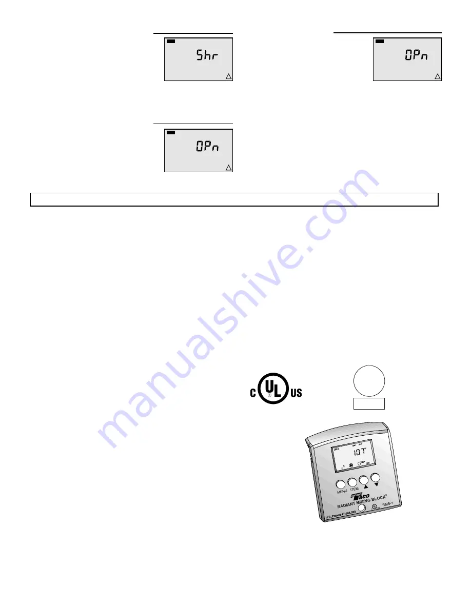
Mixing Supply Sensor Short Circuit
A short circuit has been detected in the
mixing supply sensor. The control con-
tinues to operate the injection pump at
a low speed (17 - 18%) as long as a
demand is present. To clear this error
message, correct the short circuit and
press any button on the control.
Mixing Supply Sensor Open Circuit
An open circuit has been detected in
the mixing supply sensor. The control
continues to operate the injection pump
at a low speed (17 - 18%) as long as a
demand is present. To clear this error
message, correct the open circuit and
press any button on the control.
MIX
VIEW
!
SUP
MIX
VIEW
!
SUP
VIEW
!
BOIL
Boiler Sensor Open Circuit
An open circuit has been detected in
the boiler sensor. The boiler contact is
operated as if a boiler sensor is not
installed. The control provides a boiler
enable and does not provide boiler pro-
tection. To clear this error message,
correct the open circuit and press any
button on the control. If the sensor was
deliberately removed, power down the
control for five (5) seconds and re-
power the control.
Fax: 905/564-9436
V
RMC - Radiant Mixing Control (
Variable Speed
)
Control
- Microprocessor PID control: This is not a safety (limit)
control
Ambient conditions
- Indoor use only, 32 to 185
°
F (0 to 85
°
C), <90% RH non-
condensing
Power Supply
- 120 V (ac) +/- 10% 50/60 Hz 720 VA
Var. Pump
- 120 V (ac) 1 A 1/12 hp, fuse T1 A 250 V
Sys / Pmp Relay
- 120 V (ac) 5 A 1/4 hp, pilot duty 240 VA
Boiler Relay
- 120 V (ac) 5 A 1/4 hp, pilot duty 240 VA
Demand
- 24 V (ac) 0.1 VA or Dry contact
Sensors
- NTC thermistor, 10 kohm @ 77
°
F (25C +/- 0.2
°
C) B=3892
Included
- Taco Outdoor Sensor and 2 Taco Strap-on Sensors
The installer must ensure that this control and its wiring are isolated and/or shielded from strong sources of electromagnetic noise.
Conversely, this Class B digital apparatus complies with Part 15 of the FCC Rules and meets all requirements of the Canadian Interfer-
ence-Causing Equipment Regulations. However, if this control does cause harmful interference to radio or television reception, which
can be determined by turning the control off and on, the user is encouraged to try to correct the interference by reorienting or relocating
the receiving antenna, relocating the receiver with respect to this control, and/or connecting the control to a different circuit from that to
which the receiver is connected.
MIX
SUP
DEM
VIEW
F
%
1
ITEM
MENU
RADIAN
T MIXIN
G BLOC
K
PATENT
PENDI
NG
RMB-1
TM
UL
R
C
US
Telephone: (401) 942-8000 FAX: (401) 942-2360.
T
Telephone: 905/564-9422. FAX: 905/564-9436.
V
Summary of Contents for Radiant Mixing Block
Page 2: ...2 Typical Piping ...


