background image

3

Tx should have adequate power for fl ight when the LED is on constantly. Anytime 
the LED begins to fl ash, accompanied by the sounding of an audible tone, the Tx 
battery voltage has dropped too low 

and operation of the model should NOT 

be attempted!

WARNING!


Never operate an R/C model with weak Tx batteries! 

Reduced operational range and/or possible loss of control of the 
aircraft could result. Replace weak alkaline batteries, or re-charge 
NiCd or NiMH batteries before attempting a fl ight!

If during a fl ight the Tx LED starts to fl ash, accompanied by the sounding of audible 
tones, it’s a warning that the Tx batteries have become weak and the aircraft should 
be landed as soon as possible! 

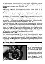
AILERON (CH1)

Controls the moveable surfaces at the end of both main wings to rotate the airplane 
about the “roll” axis (an imaginary line which extends from the airplane’s nose to 
the tail). Since every airplane is different, the aileron reversing switch must be set 
so that moving the aileron stick to the right will cause the airplane’s right aileron to 
defl ect up, thus causing the right wing to drop and the airplane will bank to the right. 
Moving the aileron stick to the left will cause the airplane’s left wing to drop and the 
airplane will bank to the left. This is one important method for turning the aircraft.

ELEVATOR (CH2)

Controls the moveable horizontal surfaces on the airplane’s tail to rotate the airplane 
about the “pitch” axis (an imaginary line extending through the center of both main 
wings, from one wing tip to the other wing tip). Position the elevator reversing switch 
so that pulling the elevator stick back (towards you) will cause the elevators to 
defl ect up, thus causing the nose of the airplane to rise. Pushing the elevator stick 
forwards (away from you) will cause the nose of the airplane to drop. When using 
the ailerons to bank the airplane’s wings, pulling the elevator stick back will help the 
aircraft maintain altitude and turn the aircraft more quickly.

THROTTLE (CH3)

Controls the speed (R.P.M.) at which the engine or electric motor operates. With 
the throttle reversing switch in the NOR position, pulling the throttle stick back will 
cause the engine’s speed to decrease. Pushing the throttle stick forward will cause 
the engine’s speed to increase.

RUDDER (CH4)

Controls the sideways movement of the airplane’s tail and will rotate the airplane 
about the “yaw axis” (an imaginary line from the top of the airplane’s fuselage to 
the bottom of the fuselage, located near the center-point of the fuselage). Position 
the rudder reversing switch so that moving the rudder stick to the right causes the 
rudder to defl ect to the right, thus causing the nose of the airplane to point to the 
right. Moving the rudder stick to the left will cause the nose of the airplane to turn 

Summary of Contents for TACJ2404

Page 1: ...to readthismanualinitsentiretybeforeuse Alsoreadandunderstand the instructions included with the model Damage resulting from misuse or modification will void your warranty FEATURES Trainer Switch LED...

Page 2: ...uired to power the Tx not included Non rechargeable 1 5V alkaline or 1 2V rechargeable nickel cadmium NiCd or nickel metal hydride NiMH cells can be used Do not mix cell types or old and new cells etc...

Page 3: ...ing the aircraft ELEVATOR CH2 Controls the moveable horizontal surfaces on the airplane s tail to rotate the airplane about the pitch axis an imaginary line extending through the center of both main w...

Page 4: ...r down and rest at any point in the range Moving the throttle trim lever slightly up or down will finely adjust the engine or motor at low speeds For safety reasons it s a good idea to use throttle tr...

Page 5: ...proper polarity Make sure the transmitter s power switch is in the OFF position Connect a compatible charge lead to the jack and follow the instructions included with the charger for charging of NiCd...

Page 6: ...power switch for the Tx being held by the student 5 Pull and hold the trainer switch on the teacher s Tx and then turn ON the teacher s Tx power switch 6 The LED on the teacher s Tx will flash 3 times...

Page 7: ...g LED is accompanied by three audible tones the elevon mixing will be active Elevon Mixing Elevator Function Aileron Function 5 To cancel all mixes repeat this procedure again When the flashing LED is...

Page 8: ...ransmitter SERVOS Center the trims on the Tx Mount the servos inside the model and connect the linkages to the servo using an appropriate length servo arm Rubber Grommet Brass Eyelet Servo Servo Servo...

Page 9: ...n and connection of the power battery GLOW ENGINES If the model is powered by a glow engine a switch harness and 4 cell battery 4 8V will be necessary to power the receiver and servos See the SERVOS A...

Page 10: ...then stays on the Rx is already bound to the Tx and you can skip to the next section Otherwise insert a small diameter screwdriver through the hole marked BIND and press the pushbutton until the Rx L...

Page 11: ...d Carefully lay the Tx on its back on the ground to prevent it from falling over and possibly dislodging the throttle stick from the low position which would create a safety hazard Make sure all devic...

Page 12: ...ise the aircraft could become out of control and cause a safety hazard Move the throttle stick and throttle trim lever to minimum position to stop the glow engine or shut down the ESC Once the propell...

Page 13: ...for recreational or competition activity 2 The maximum takeoff weight of a model aircraft including fuel is 55 pounds except for those flown under the AMA Experimental Aircraft Rules 3 I will abide b...

Page 14: ...ll model flying shall be conducted in a manner to avoid overflight of unprotected people 2 I will have completed a successful radio equipment ground range check before the first flight of a new or rep...

Page 15: ...he entire flight maintaining visual contact without enhancement other than by corrective lenses that are prescribed for the pilot No model aircraft shall be equipped with devices which allow it to be...

Page 16: ...AM2500 Y Harness Futaba J TACL0624 Tactic TR624 6 Channel 2 4GHz Receiver TACM2000 Switch Harness with Futaba J Plugs No Charge Lead TACM2001 Switch Harness with Charge Lead Futaba J Plugs TACM2020 4...

Page 17: ...ultaneously NEVER operate R C equipment if you are physically impaired as it could pose a safety hazard to yourself or others in the area NEVER allow small children to operate control model R C equipm...

Page 18: ...range operate the model more closely to the transmitter Outside radio interference from pagers strong industrial or other commercial transmitters in the area check your local R C club regarding local...

Page 19: ...4B CE COMPLIANCE INFORMATION FOR THE EUROPEAN UNION Instructions for Disposal of Waste Equipment by Private Users in the European Union This symbol on the product or its packaging indicates this produ...

Page 20: ...ve due to those causes You will be required to provide proof of purchase invoice or receipt This warranty does not cover damage caused by abuse misuse alteration or accident If there is damage stemmin...

Reviews: