9
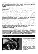
sticks in fl ight, it should be re-adjusted so as not to drain excessive current from the
battery and thus shorten fl ight time.
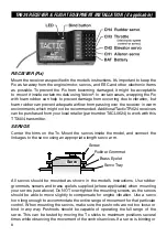
Rudder
Servo
(Ch4)
Receiver
Throttle
Servo
or ESC
(Ch3)
Elevator
Servo
(Ch2)
Aileron
Servo
(Ch1)
Switch Harness
To Rx Battery
To Charger
Connect the servos to the Rx as shown. Route the wires so they do not interfere
with any moving parts. Move the Tx trims to fi nely adjust the servo’s center point as
needed to match the installation. See the
SERVOS AND ACCESSORIES
section on
page 16 for a full list of optional servos.
ELECTRONIC SPEED CONTROL (ESC)
If the model is electric powered, an optional ESC will be necessary to control speed
of the electric motor and to divert power to the receiver and servos. Connect the
receiver plug on the ESC to the slot marked CH3 (throttle) on the receiver. Center
the transmitter’s throttle trim and follow the ESC instructions for proper operation
and connection of the power battery.
GLOW ENGINES
If the model is powered by a glow engine, a switch harness and 4-cell battery
(4.8V) will be necessary to power the receiver and servos. See the
SERVOS AND
ACCESSORIES
section for suggested options.
ON/OFF SWITCH HARNESS AND BATTERIES
Many ESCs include a built-in ON/OFF power switch. Glow powered airplanes
require a separate battery to power the receiver and servos, and using a separate
switch harness is convenient for turning on and off power to the receiver.
A switch harness and 4-cell battery holder is included with the TTX404 radio system.
Refer to the model’s instructions for the optimum location to mount the battery, Rx, and
switch harness for optimum weight distribution in the model. Locate the switch well
away from the propeller and the exhausts from a glow engine. Cut a hole in the side of
the fuselage large enough to allow the switch’s lever to move freely and fully from end-
to-end. If the switch harness includes mounting screws, be sure not to cut the hole so
long that it would prevent the mounting screws from being installed fi rmly.

