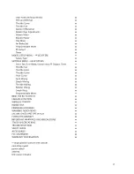
cursor. Pressing
←
or
→
can move the cursor freely. Repeat as necessary for up to 8 characters. Pressing CLEAR
will move the cursor back one space and erase the character in that space. Press ESC when finished.
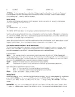
STICK MODE:
The TTX650 is factory set to
Mode 2 configuration, but can be changed to
Mode 1 (elevator on left, throttle on right). To
change modes in the programming, move the
cursor to the STICK MODE line, highlight and
press ENTER, then press
↑
+ or
↓ ‐
.
Press
ENTER to confirm.
In addition to programming changes, stick
mode changes require reversal of the throttle
ratchet and elevator arm/spring. Refer to the
CASE SEPARATION AND ASSEMBLY section on
page xx for opening and safely re-assembling the case after the mechanical adjustments are made.
Failure to do
this properly can cause permanent damage to the radio and void the warranty.
rudder
Mode 1: elevator
Mode 2: throttle
aileron
Mode 1: throttle
Mode 2: elevator
LEFT STICK
RIGHT STICK
NORMAL STICK CONFIGURATIONS
Throttle ratchet:
The long metal bar resting across the throttle gimbal must be moved to the other gimbal.
Carefully remove the screws at each end of the bar. Re-locate the bar to the other gimbal and install across the
ratcheted surface of the gimbal as shown. Re-install both screws. Carefully install the screw at top until snug –
do
not over-tighten!
The screw at bottom should be tightened until the vertical movement of this stick has the
desired amount of resistance.
Elevator arm and spring:
The black plastic arm and spring must be re-located from the elevator gimbal to the
opposite gimbal. Using a pair of needle nose pliers or hemostats, carefully grip the end of the spring which is
looped over the end of the black plastic arm and gently lift it off the arm. Then slide the spring towards the center
of the gimbal to remove it from the gimbal. Set the spring aside.
Raise the plastic arm to a vertical position. Slide the arm towards the center of the gimbal to remove it from its
mounting pin.
Rotate the arm 180 degrees to mount it to the opposite gimbal as shown. While in the vertical position, slide the
arm over the mounting pin on the opposite gimbal. Lay the arm down across the gimbal.
Gripping one loop on the end of the spring, carefully lower the opposite loop of the spring into the gimbal to
slide it over the appropriate mounting pin. With the spring holding onto the pin inside the gimbal, carefully
stretch the spring and hook the loop over the end of the plastic arm. Confirm the arm and spring are mounted
properly by moving this stick and ensuring all movement is smooth but with resistance from the spring.
Close the transmitter as explained in the CASE SEPARATION AND ASSEMBLY section.
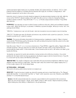
CONTRAST:
Adjust the LCD's contrast level for optimum viewing.
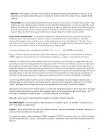
BEEP VOLUME:
Adjust the loudness of the radio's beeper as desired. This volume setting affects all tones that
are emitted from the radio including
trim adjustments, alarms
, programming changes, etc.
7

