background image

T

ac

tic

al

 C
ont
rol

s L

im

ite

d

P

ow
er

 E

nc
los

ur

A

ss

em

bl

y I
ns

tr

uc
tion 
M

anua
l

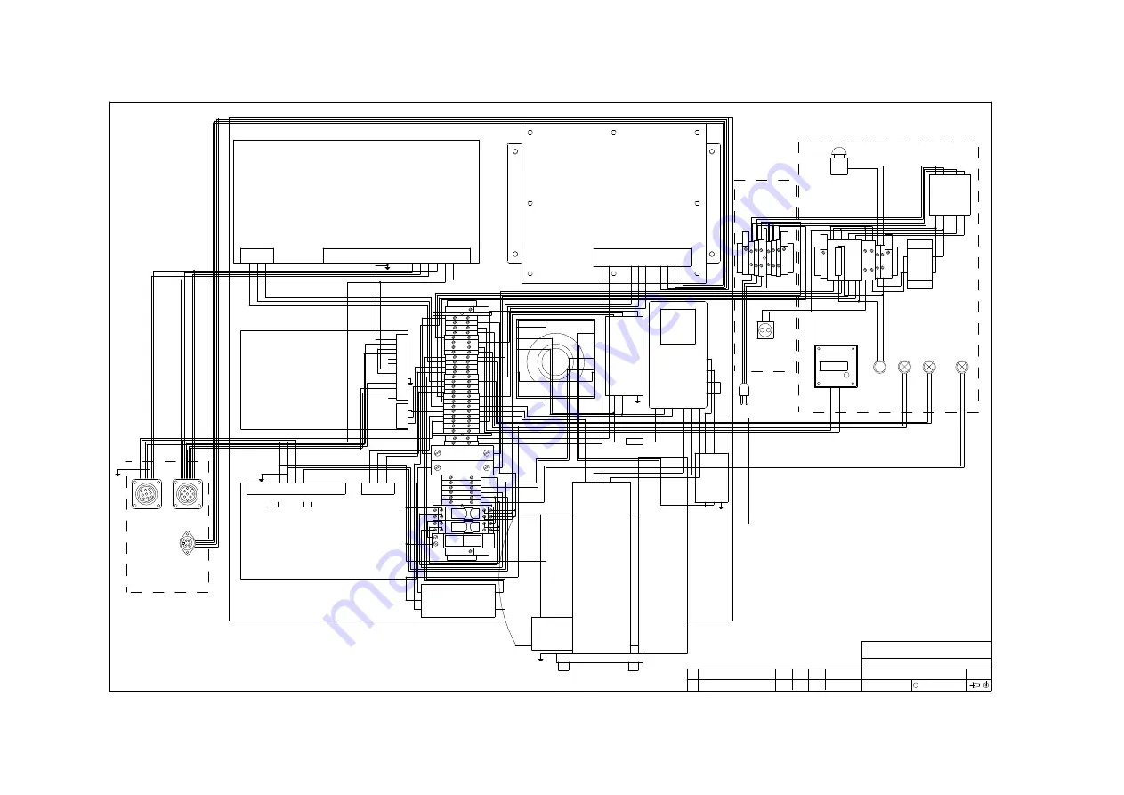
Wi
ri

n

g

 d

ia

g

ra

m

MOTOR

PS3

DIMMER

INVERTER

CONTROLLER

TB1

A1

A3

A2

BACK PLATE

SMS300/12

SMS100/24

M1

PS2

PS1

SLMC75R/06

1

2

3

4

5

GLAND PLATE

SK3

1

2

3

4

5

6

7

8

9

SK2

1

2

3

4

5

6

7

8

9

SK1

FILTER

FL3

FILTER

FL2

5
6
7
8

25
26

FILTER

FL1

VIEW FROM INSIDE

1 2 3

4 5 6

VIEW FROM INSIDE

INSIDE CABINET

1
2
3
4

9

10
11
12
13
14
15
16
17
18
19
20
21
22
23
24

CB1

0

-O

FF

1

-O

N

CB2

0

-O

FF

1

-O

N

27
28
29
30
31
32

RL1

RL2

PB1

RP330024

RP420024

R1

SW1

MAINS SWITCH

C1

CONTACTOR

SK4

SCHUKO SOCKET

TB2

TB3

TX1

TRANSFORMER

1 2

FS1 FS2

L1

L3

ON THE DOOR

VIEW FROM INSIDE

L2

TIMER

COUNTER

TEI

SB2

SB1

EMERGENCY STOP

1

2

1

2

24

21

14

11

24

21

14

11

22

A2

A1

12

22

A2

A1

12

1 5

3 N7

2 6

4 N8

1

2

7

5

3

4 6 8

A1

A2

0

240

0

24

-4

-3

1

2

3

E

N

L

5
3
1

E

N

L

5

4

3

L

N

E

20

21

E

14/L

16/N

STF

SD

V

E

2

5

1

2

3

4

5

6

7

8

9 10 11 12 13 14 15 16

0V

1

9

1

2

3

4

5

6

7

8

V+

V+

V- V-

S-

S+

S+

S-

V-

V-

V+

V+

+5

+5

+5

0V

0V

0V

2

3

4

5

6

7

8

9

10

-12V

-5V

0V

0V

11

12

13

0V

N

E

6

7

N

9

10 11

12

2

1

L

5

STROBE

CLOCK

0V

DATA

OP

8

4

3

X

X

X

TO CABINET EARTH STUD
& DOOR EARTH STUD

23

24

1

5

1

9

1

9

L1 N

E

U

V W

U

W

N

LINE

L

N

L

E

N

L

N

L

E

LOAD

L

N

E

L

N

LINE

LOAD

LOAD

LINE

E

2

1

1

2

3

4

All Rights Reserved.

C

Filename:

Size:

Drawing No.:

Title:

Tactical Controls Limited

Rev.

Description

Iss.

Chk.

Auth.

Date

A0

PEA - POWER ENCLOSURE ASSEMBLY WIRING

PEA\DWG\WIRING

WIRING

ALL DIMENSIONS ARE IN MM.  GENERAL TOLERANCE  X = +/-0.5  X.X = +/-0.05

2

1

LINK L1 AND L2; NEW PUSH BUTTON

3.4

3-NOV-1997

20M 2 CORE BLACK

MP1

SCHUKO PLUG

15M 3 CORE BLACK

pe
a\

im

P

age
 10

16 M

ar

ch 1998

Is

sue
 4.0

Summary of Contents for PEA

Page 1: ...ent contains proprietary information which is protected by copyright All rights reserved This document or parts thereof may not be reproduced in any form without written permission of the publishers The information in this document is subject to change without notice and should not be construed as a commitment by Tactical Controls Limited Tactical Controls Limited shall not be liable for errors co...

Page 2: ...with its controller and Inverter and Mirror protection circuitry Mains distribution Elapsed time counter mains switch and the mains circuit breakers Block diagram ALL DIMENSIONS ARE IN MM GENERAL TOLERANCE X 0 5 X X 0 05 All Rights Reserved C Filename Size Drawing No Title Tactical Controls Limited Rev Description Iss Chk Auth Date A3 DIMMER CONTROL PEA BLOCK DIAGRAM PEA DWG BLOCK BLOCK DC SUPPLIE...

Page 3: ...nts Two poles of distributed mains 2 5 or 4 mm2 type with a minimum of Pole 1 8 live terminals points 8 neutral terminals points Pole 2 8 live terminals points 8 neutral terminals points Common earth consisting of 16 earth terminals points Four terminals points for dimmer output Two 10 amp Circuit breakers Twelve terminals points for mirror position sensor input limit switch input and mirror prote...

Page 4: ...hole at the back of the cabinet and floor free standing on 4 rubber feet 17 The paint finish is colour Green RAL 6031 Matt 18 The casing and door are earthed 19 Internal wiring are made to drawings 46 486 649 197 20 The following labels are located at suitable locations and without any language dependant text High voltage symbol inc voltage range 215 240V and frequency 50Hz Earth Point symbol 21 S...

Page 5: ...N 1997 RAL6031 PAINT FINISH 300 0 700 0 1 KEY OPERATED DOOR LOCK 2 DOOR HINGES 700 0 20 OFF 3X25MM AIR VENT ON BOTH SIDES OF CABINET ON A 240X120 GLAND PLATE STEEL CABINET TO BE BOTH WALL MOUNTED THROUGH 4 X M8 INVERTED KEYHOLE AT FOUR CORNERS AND FREE STANDING ON 4 RUBBER FEET 8 PG11 CABLE GLANDS D SHAPED DOOR HANDLE ELAPSED TIME COUNTER 20 0 150 0 M5X15 STUD ON BOTH SIDES OF CABINET 55 0 590 0 5...

Page 6: ... mains cable with a Schuko plug fitted 2 Mains distribution to Compressor L N and E on TB1 1 5 and 22 Mains distribution to Instructors station L N and E on TB1 11 15 and 23 Mains distribution to Firing station L N and E on TB1 12 16 and 24 3 DC power supplies 12V 5V 5V and 12 sense Panel mounted socket SK1 12V 12V 24V and earth Panel mounted socket SK2 24V for comms control Terminal 2 and 7 on PS...

Page 7: ...isabled The fault lamp is lit indicating the presence of mirror fault Provided the fault no longer exists the latching circuit can be cleared by either pressing the Reset button or turning off the power Please refer to the following diagram for further details ULTRA SONIC TRANSDUCER LATCHING RELAY FAULT ALL DIMENSIONS ARE IN MM GENERAL TOLERANCE X 0 5 X X 0 05 2 LAMP L3 2 RESET BUTTON PB1 1 LIMIT ...

Page 8: ...4 0 2 2 0 C a b in e t E a rth TB 1 2 0 B o o tla c e C a b in e t M 5 rin g G N Y L A W G 1 6 2 1 P S 1 E a rth TB 1 2 1 B o o tla c e P S 1 E M 4 fo rk G N Y L A W G 1 6 2 1 M o to r E a rth TB 1 2 1 B o o tla c e M 1 E M 4 rin g G N Y L A W G 1 6 2 2 S K 2 E a rth TB 1 2 2 B o o tla c e S K 2 9 C rim p G N Y L 2 4 0 2 2 2 F L 1 E a rth TB 1 2 2 B o o tla c e F L 1 E B o o tla c e G N Y L A W G ...

Page 9: ... 1 L b la d e TB 2 4 L b la d e B ro w n A W G 1 6 5 8 S w it c h 1 L 1 t o TB 2 TB 2 1 L b la d e S W 1 1 M 4 fo rk B ro w n A W G 1 6 5 8 S w it c h 1 L 2 t o TB 2 TB 2 4 L b la d e S W 1 3 M 4 fo rk B ro w n A W G 1 6 5 9 S w it c h 1 N 1 t o TB 2 TB 2 2 L b la d e TB 2 5 L b la d e B lu e A W G 1 6 5 9 TB 2 N 1 t o N 2 TB 2 5 L b la d e S W 1 5 M 4 fo rk B lu e A W G 1 6 5 9 S w it c h 1 N 2 t...

Page 10: ...24 21 14 11 22 A2 A1 12 22 A2 A1 12 1 5 3 N7 2 6 4 N8 1 2 7 5 3 4 6 8 A1 A2 0 240 0 24 4 3 1 2 3 E N L 5 3 1 E N L 5 4 3 L N E 20 21 E 14 L 16 N STF SD V E 2 5 1 2 3 4 5 6 7 8 9 10 11 12 13 14 15 16 0V 1 9 1 2 3 4 5 6 7 8 V V V V S S S S V V V V 5 5 5 0V 0V 0V 2 3 4 5 6 7 8 9 10 12V 5V 0V 0V 11 12 13 0V N E 6 7 N 9 10 11 12 2 1 L 5 STROBE CLOCK 0V DATA OP 8 4 3 X X X TO CABINET EARTH STUD DOOR EAR...

Page 11: ... Reliability MTBF of not less than 1000 hours Supply 215 to 240Vrms 5 50Hz 1 Temperature 0 to 50 ºC operating 20 to 65 ºC storage Dimensions 700mm H x 700mm W x 300mm D Mounting positions Wall mounted on fixing centres 590 x 600mm or free floor standing on 4 rubber feet Weight 65Kg max References Critical Item Design Specification CIDS for the Power Cabinet PCAB HWCI of the Power and Air PAIR HWCI...

Page 12: ...ion Ordering code PEA You are welcome to order the unit by code or description PEA Power Enclosure Assembly Supplier information Tactical Controls Limited Unit 4 Marlborough Road Lancing West Sussex BN15 8TR England Tel 01903 750800 Fax 01903 750678 pea im Page 12 16 March 1998 Issue 4 0 ...

Reviews: