F - 4
F - 4
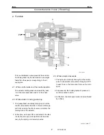
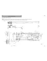
Counterbalance Valve (W inch)
10
W119-0501E
101.Casing
151.Plug
152.Plug
161.O-ring
162.O-ring
163.O-ring
164.O-ring
165.O-ring
171.Hex. socket head bolt
172.Square spring washer
201.Cover
202.Cover
203.Spacer
204.Spacer
252.Air bleeder screw seat
253.Plug
256.Air bleeder screw
261.O-ring
262.O-ring
271.Hex. socket head bolt
272.Square spring washer
273.Hex. socket head bolt
274.Square spring washer
301.Spool
302.Pilot piston
312.Steel ball
321.Spring
322.Spring
351.Orifice
354.Orifice
355.Orifice
361.O-ring
362.O-ring
511.Plunger
514.Seat
521.Spring
551.Plug
562.O-ring
563.Backup ring
600.Relief valve
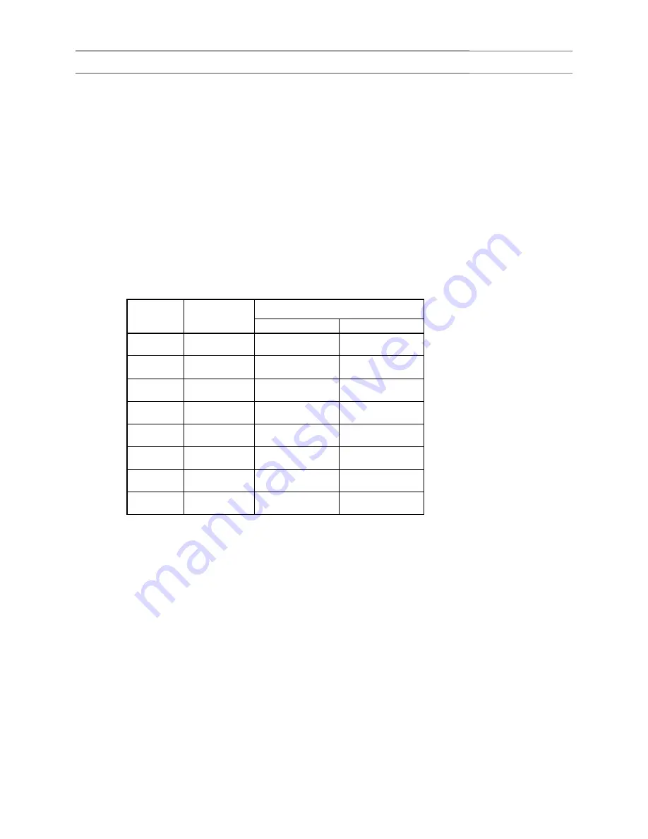
Thread size and tightening torque
Tightening torque
Sign / port
Thread size
N-m ft-lbf
151, 152
G3/8
69 - 79
51 - 58
171
M12
64 - 74
47 - 54
252
G1/4
34 - 38
25 - 28
253
G1/4
34 - 38
25 - 28
256
M10
14 - 18
10 - 13
271, 273
M12
88 - 108
65 - 80
551
M33
181 - 211
134 - 156
600
M33
166 - 186
123 - 137
2. Function
2.1 Balancing and holding functions
1. During hoisting down, this valve selectively opens
and closes the motor outlet passage in
accordance with the pressure level of the motor
inlet pressure to control the speed of the load and
to prevent the load from falling under weight faster
than the hydraulic motor driving speed.
2. When the inlet pressure is below a certain level,
this valve closes the return passage to hold the
load at a desired position.
2.2 Overload relief function
When the circuit pressure rises above the preset
overload relief level, this valve vents it to protect
the circuit.
Summary of Contents for TR-800XXL4
Page 47: ...B 9 B 9 Rotary Joint 27 W181 0440E Upper view A Lower view B...
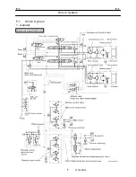
Page 119: ...F 1 F 1 Winch System 1 WF02 0251E F 1 Winch System 1 General Hydraulic Circuit for Winch...
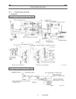
Page 135: ...G 1 G 1 Telescoping System 3 WG02 0321E Telescoping cylinder at select...
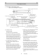
Page 143: ...G 2 G 2 Boom Five Section Boom G 2 11 W536 0761E 11...
Page 196: ...13 13 W701 0220E K 2 K 2 Air Conditioner K 2 4 Layout 4 1 Overall layout 4 345 107 61000...
Page 197: ...14 14 W701 0220E K 2 K 2 Air Conditioner K 2 4 2 Overall layout 0 345 110 73000...
Page 198: ...15 15 W701 0220E K 2 K 2 Air Conditioner K 2 4 3 Evaporator section 5 345 107 02000...
Page 199: ...16 W701 0220E K 2 K 2 Air Conditioner 5 Compressor Assy...
Page 200: ...17 17 W701 0220E K 2 K 2 Air Conditioner K 2 6 Evaporator Assy...
Page 201: ...18 18 W701 0220E K 2 K 2 Air Conditioner K 2 7 Condenser Assy...
Page 202: ...19 19 W701 0220E K 2 K 2 Air Conditioner K 2 8 Electric 8 1 Electric circuit 0 363 205 60030...
Page 203: ...20 20 W701 0220E K 2 K 2 Air Conditioner K 2 8 2 Main harness A...
Page 204: ...21 21 W701 0220E K 2 K 2 Air Conditioner K 2 8 3 Main harness B...
Page 222: ...39 K 2 K 2 K 2 Air Conditioner 39 W701 0220E 12 2Compressor diagnosis chart 1 2...
Page 223: ...40 K 2 K 2 K 2 Air Conditioner 40 W701 0220E Compressor diagnosis chart 2 2...
Page 224: ...K 2 K 2 Air Conditioner 41 W701 0220E 13 Troubleshooting...
Page 225: ...K 2 K 2 Air Conditioner 42 W701 0220E...
Page 226: ...K 2 K 2 Air Conditioner 43 W701 0220E...
Page 227: ...K 2 K 2 Air Conditioner 44 W701 0220E...
Page 228: ...K 2 K 2 Air Conditioner 45 W701 0220E...
Page 229: ...K 2 K 2 Air Conditioner 46 W701 0220E...
Page 237: ...L 1 L 1 Control System 2 WL02 0090E 2 General of pneumatic control devices Pneumatic Circuit...
Page 291: ...T 5 T 5 Air Dryer 26 W232 0032E Heater View A 39 C B B A 58 59 2 IW232 0030E03...
Page 370: ...8 8 WZ03 3300E Z 5 Z 5 Electric Circuit MDT Carrier Upper Z 5 IWZ03 3300E01...
Page 372: ...10 Z 6 Z 6 Electric Circuit MDT Carrier Lower Z 6 10 WZ03 3310E IWZ03 3310E01...
Page 400: ...38 Z 24 Z 24 Harness Lower Sub 38 WZ04 2450E Z 24 Z 24 Harness Lower Sub 2 349 310 00200...


