7
W305-0451E
H - 2 .
H - 2 .
Boom Length and Angle Detector
2.5 Reassembling potentiometer
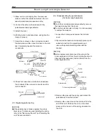
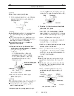
1. Install a new potentiometer.
[NOTICE]
To avoid exposing the potentiometer to high
temperature for a long time, solder the
potentiometer terminal and the lead wires quickly.
Fix the potentiometer terminal including the lead
wires to the bracket using insulating sealant.
Recommended sealant: Shin-Etsu Silicone
KE45RTV (Shin-Etsu Chemicals Industry)
IW305-0230E14
Potentiometer
Bracket
Insulating sealant
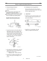
2. Loosen the set screws on the reducer side and
potentiometer side to allow both gears to idle.
Check that the gear on the potentiometer side is
spring-returned to the original position after it is
rotated a quarter turn by finger and released. If it
is not returned, loosen the bolt and adjust the
position of the bracket.
IW305-0230E15
Bracket
Spring
Bolt
Gear B
Gear A
3. Fix the gear in the notched section of the speed
reducer shaft using a set screw. Apply thread
locking agent to the set screw.
Tightening torque : 1.18N-m {0.87ft-lbf}
4. Follow the same procedure as described in the
step 12. and below of the "Installing the cord"
section.
2.6 Replacing the boom angle detector
Disconnect the lead wires to the boom angle
detector from the pin terminal section, and replace
the boom angle detector assy.
3. Adjustment
1. Adjust the cord lock so that the 0-marker on the
cord is on the edge of the cord guide when the
boom is fully retracted.
0-marker
Cord lock
IW305-0230E16
2. Adjust the boom length display of the AML.
(Refer to the repair manual of the AML.)
△
0
361-322-80000
Summary of Contents for TR-800XXL4
Page 47: ...B 9 B 9 Rotary Joint 27 W181 0440E Upper view A Lower view B...
Page 119: ...F 1 F 1 Winch System 1 WF02 0251E F 1 Winch System 1 General Hydraulic Circuit for Winch...
Page 135: ...G 1 G 1 Telescoping System 3 WG02 0321E Telescoping cylinder at select...
Page 143: ...G 2 G 2 Boom Five Section Boom G 2 11 W536 0761E 11...
Page 196: ...13 13 W701 0220E K 2 K 2 Air Conditioner K 2 4 Layout 4 1 Overall layout 4 345 107 61000...
Page 197: ...14 14 W701 0220E K 2 K 2 Air Conditioner K 2 4 2 Overall layout 0 345 110 73000...
Page 198: ...15 15 W701 0220E K 2 K 2 Air Conditioner K 2 4 3 Evaporator section 5 345 107 02000...
Page 199: ...16 W701 0220E K 2 K 2 Air Conditioner 5 Compressor Assy...
Page 200: ...17 17 W701 0220E K 2 K 2 Air Conditioner K 2 6 Evaporator Assy...
Page 201: ...18 18 W701 0220E K 2 K 2 Air Conditioner K 2 7 Condenser Assy...
Page 202: ...19 19 W701 0220E K 2 K 2 Air Conditioner K 2 8 Electric 8 1 Electric circuit 0 363 205 60030...
Page 203: ...20 20 W701 0220E K 2 K 2 Air Conditioner K 2 8 2 Main harness A...
Page 204: ...21 21 W701 0220E K 2 K 2 Air Conditioner K 2 8 3 Main harness B...
Page 222: ...39 K 2 K 2 K 2 Air Conditioner 39 W701 0220E 12 2Compressor diagnosis chart 1 2...
Page 223: ...40 K 2 K 2 K 2 Air Conditioner 40 W701 0220E Compressor diagnosis chart 2 2...
Page 224: ...K 2 K 2 Air Conditioner 41 W701 0220E 13 Troubleshooting...
Page 225: ...K 2 K 2 Air Conditioner 42 W701 0220E...
Page 226: ...K 2 K 2 Air Conditioner 43 W701 0220E...
Page 227: ...K 2 K 2 Air Conditioner 44 W701 0220E...
Page 228: ...K 2 K 2 Air Conditioner 45 W701 0220E...
Page 229: ...K 2 K 2 Air Conditioner 46 W701 0220E...
Page 237: ...L 1 L 1 Control System 2 WL02 0090E 2 General of pneumatic control devices Pneumatic Circuit...
Page 291: ...T 5 T 5 Air Dryer 26 W232 0032E Heater View A 39 C B B A 58 59 2 IW232 0030E03...
Page 370: ...8 8 WZ03 3300E Z 5 Z 5 Electric Circuit MDT Carrier Upper Z 5 IWZ03 3300E01...
Page 372: ...10 Z 6 Z 6 Electric Circuit MDT Carrier Lower Z 6 10 WZ03 3310E IWZ03 3310E01...
Page 400: ...38 Z 24 Z 24 Harness Lower Sub 38 WZ04 2450E Z 24 Z 24 Harness Lower Sub 2 349 310 00200...

