Y - 5
Y - 5
Adjustment and Checks
22
WY05-1390E
5. Engine speed (and governer setting)
[NOTICE]
Before checking the engine speed, run the engine
to warm it up. (Light weight grease should reach
approximately 50°C (122°F).)
1. No-load Max. speed
• PTO - OFF
: 2860 ± 40 min
-1
• PTO - ON
: 2150 - 2200 min
-1
2. Idling speed
: 645 - 695 min
-1
(PTO - OFF)
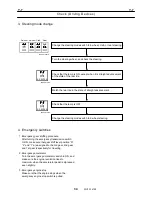
3. Stall speed
(1) Set the switches and levers as described below.
• PTO switch
: OFF
• Shift lever
: 2nd gear
• Drive speed selector switch
: 4WD Hi
• Service brake
: ON
(2) Depress the accelerator pedal all the way. Check
the speed when the engine speed has stabilized.
Max. speed standard when stalled:
Approx. 2160 min
-1
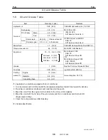
6. Torque converter and transmission
6.1 Maximum allowable speed
Units: MPH (km/h)
Shift position
Hi position
Lo position
1 5.5
(8.9)
1.6 (2.5)
2 11.6
(18.5)
3.2 (5.1)
D 22.5
(36.2)
6.2 (10.0)
R 3.9
(6.2)
1.6 (2.5)
[NOTICE]
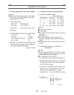
Engine speed: 2600 min
-1
Gauge display
Pay attention to the tachometer and do not overrun
the engine.
(Max. 2900 min
-1
)
Drive-speed selection must be done with the
vehicle at a complete stop and with the brakes not
applied.
The mechanism does not allow 2WD selection in Lo
position.
6.2 Adding oil to the torque converter and
transmission
[NOTICE]
When checking the oil level, turn PTO OFF. Check
at an oil temperature of 50°C, once the oil level has
stabilized after the engine is started.
Do not add too much or too little oil.
Do not allow dust or water to enter when adding oil.
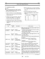
1. With the engine stopped, add oil to the oil injection
port in the top of the T/C, to the prescribed level
on the T/M oil level gauge.
2. Put the T/M in neutral and start the engine. While
idling (670 min
-1
), continue to add oil. Check that
the oil level has stabilized within the range
indicated by the * mark on the T/M oil level gauge.
Total oil volume:
approx.46L (12.2gal)
Summary of Contents for TR-800XXL4
Page 47: ...B 9 B 9 Rotary Joint 27 W181 0440E Upper view A Lower view B...
Page 119: ...F 1 F 1 Winch System 1 WF02 0251E F 1 Winch System 1 General Hydraulic Circuit for Winch...
Page 135: ...G 1 G 1 Telescoping System 3 WG02 0321E Telescoping cylinder at select...
Page 143: ...G 2 G 2 Boom Five Section Boom G 2 11 W536 0761E 11...
Page 196: ...13 13 W701 0220E K 2 K 2 Air Conditioner K 2 4 Layout 4 1 Overall layout 4 345 107 61000...
Page 197: ...14 14 W701 0220E K 2 K 2 Air Conditioner K 2 4 2 Overall layout 0 345 110 73000...
Page 198: ...15 15 W701 0220E K 2 K 2 Air Conditioner K 2 4 3 Evaporator section 5 345 107 02000...
Page 199: ...16 W701 0220E K 2 K 2 Air Conditioner 5 Compressor Assy...
Page 200: ...17 17 W701 0220E K 2 K 2 Air Conditioner K 2 6 Evaporator Assy...
Page 201: ...18 18 W701 0220E K 2 K 2 Air Conditioner K 2 7 Condenser Assy...
Page 202: ...19 19 W701 0220E K 2 K 2 Air Conditioner K 2 8 Electric 8 1 Electric circuit 0 363 205 60030...
Page 203: ...20 20 W701 0220E K 2 K 2 Air Conditioner K 2 8 2 Main harness A...
Page 204: ...21 21 W701 0220E K 2 K 2 Air Conditioner K 2 8 3 Main harness B...
Page 222: ...39 K 2 K 2 K 2 Air Conditioner 39 W701 0220E 12 2Compressor diagnosis chart 1 2...
Page 223: ...40 K 2 K 2 K 2 Air Conditioner 40 W701 0220E Compressor diagnosis chart 2 2...
Page 224: ...K 2 K 2 Air Conditioner 41 W701 0220E 13 Troubleshooting...
Page 225: ...K 2 K 2 Air Conditioner 42 W701 0220E...
Page 226: ...K 2 K 2 Air Conditioner 43 W701 0220E...
Page 227: ...K 2 K 2 Air Conditioner 44 W701 0220E...
Page 228: ...K 2 K 2 Air Conditioner 45 W701 0220E...
Page 229: ...K 2 K 2 Air Conditioner 46 W701 0220E...
Page 237: ...L 1 L 1 Control System 2 WL02 0090E 2 General of pneumatic control devices Pneumatic Circuit...
Page 291: ...T 5 T 5 Air Dryer 26 W232 0032E Heater View A 39 C B B A 58 59 2 IW232 0030E03...
Page 370: ...8 8 WZ03 3300E Z 5 Z 5 Electric Circuit MDT Carrier Upper Z 5 IWZ03 3300E01...
Page 372: ...10 Z 6 Z 6 Electric Circuit MDT Carrier Lower Z 6 10 WZ03 3310E IWZ03 3310E01...
Page 400: ...38 Z 24 Z 24 Harness Lower Sub 38 WZ04 2450E Z 24 Z 24 Harness Lower Sub 2 349 310 00200...

