6
Z-4.
Z-4.
Z-4.
0
344-121-81000
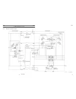
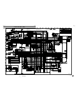
Electric Circuit (AML, Crane)
6
WZ03-3290E
2
1
3
4
5
6
7
9
8
10
11
12
13
14
16
15
17
18
19
20
21
22
23
2
1
3
4
5
6
7
9
8
10
11
12
13
14
16
15
17
18
19
20
21
22
23
A
B
C
D
E
F
G
H
I
J
K
L
M
N
O
P
A
B
C
D
E
F
G
H
I
J
K
L
M
N
O
P
3 1 4 2
R
1 2
1
2
2
1
2
1
3 1 4 2
R
CN667 AML connector 3
CN666 AML connector 2
AML connector 1
AML
AML
AML
AML
AML
AML
AML
CN665
Di23 Main rope run-out detection
Di22 Counterweight equipped detection
Di21 Jib state switch
CNTLSLD
(CNTL6N)
(CNTL6P)
(CNTL5N)Swing relief proportional control valve COM
(CNTL5P)Swing relief proportional control valve output
NC
NC
Di28 Top boom extension
Di27 Telescoping system select
Di26 Rope run-out release
Di25 Emergency outrigger state control
NC
Di24 Aux. rope run-out detection
12
11
10
9
13
21
20
19
18
17
16
15
14
24
23
22
SIF2TXD-
Di16 Aux. winch employed
SIF2SRC
SIF2GND
(CNTLSLD)
(CNTL4N)Boom lowering proportional control valve COM
(CNTL4P)Boom lowering proportional control valve output
(CNTL3N)Boom raising proportional control valve COM
(CNTL3P)Boom raising proportional control valve output
Di20 Swing left
Di19 Swing right
Di18 Boom lowering
Di17 Boom raising
Di15 Boom extention
(CNTL2N)Left swing proportional control valve COM
(CNTL2P)Left swing proportional control valve output
(CNTL1N)Right swing proportional control valve COM
(CNTL1P)Right swing proportional control valve output
Di14 Aux. winch hoisting down detection
Di13 Aux. winch hoisting up detection
Di12 Main winch hoisting down detection
TR2 External indicator(90
〜
100%)
TR3 External indicator(100%
〜
)
TR4 Output spare
TR7 Output spare
TR6 Aux. winch employed
TR5 Output spare
TR1 External indicator(
〜
90%)
SIF2SLD
SIF2RXD-
12
11
10
13
34
33
32
31
30
29
28
27
26
25
24
23
22
21
20
19
18
17
16
15
14
4
3
2
1
5
6
7
8
TR8 Output spare
Telescoping system select
Auto. stop 1 (AML vent)
Telesclping control output
Output spare
3A
RLY8
3A
3A
3A
RLY7
RLY6
RLY5
RLY4
RLY3
RLY2
RLY1
Jib setting
Buzzer output (AML alarm)
Buzzer output (Over wind alarm)
Output spare
ANAINA Boom length input
DET1GND
SIF1RXD-
SIF1TXD-
SIF1SRC
SIF1GND
NC
NC
MOSLDSLD
MOINN/ANAINH (Elevating cylinder lowering pressure input)
MOINP/ANAING (Elevating cylinder raising pressure input)
MOSRC/DET3SRC
MOGND/DET3GND
GND
GND
Di10 input spare
Di9 Over-front detection
Di8 Jib stowed detection
Di7 Elevating slow stop cancel input
Di6 AML override
Di5 Overwind cutout (anti-twoblock) disable
NC
ACC Swing stop cancel input
TC
RB
RB
MB
MB
Di4 Swing free input
SIF1SLD
Di3 3rd/top boom full retraction detection
Di2 2nd boom full retraction detection
Di1 Overwind (two-blocking) detection
AML-L
Ⅱ
B/C
ANAINB Boom angle input
ANAIND Swing angle 2 input
ANAINF Input spare
ANAINE Main pressure input
DET2GND
DET1SRC
ANAINC Swing angle 1 input
DET1SLD
DET2SLD
DET2SRC
6
5
4
3
2
1
7
8
9
12
11
10
13
14
15
16
17
18
19
20
21
22
23
24
25
26
27
28
29
30
31
32
33
34
35
36
37
38
39
40
41
42
43
44
45
8
7
1
2
3
4
5
6
9
Di11 Main winch hoisting up detection
2A
2A
Current
supply
amplifier
Current
Supply
amplifier
Current
Supply
amplifier
2A
2A
2A
3A
3A
Stabilizing power
supply circuit
1
2
1
2
1 2
1
3
4
2
5
1
3
4
5
2
5
4
3
6
2
1
5
2
3
4
1
2
3
2
1
Output
-
+
L
B
Br
1 2
1 2
1 2
2
1
2
1
2
1
2
1
2
1
2
1
2
1
2
1
M
M
3
2
1
Output
-
+
L
B
Br
3
2
1
Output
-
+
L
B
Br
3
2
1
Output
-
+
L
B
Br
-
Output
+
2
1
3
3
1
2
R
W
B
+
-
Output
3
1
2
R
W
B
+
-
Output
3
1
2
R
W
B
+
-
Output
1
3
4 2
R
3 1 4 2
R
1
3
4 2
R
3 1 4 2
R
3 1 4 2
R
3 1 4 2
R
1
3
4
2
5
1
3
4
5
2
5
4
3
6
2
1
5
2
3
4
1
2
1 2
2
1
SOL
3 1 4 2
R
3 1 4 2
R
3 1 4 2
R
1 2
5
6
3 1 4 2
R
1
4
2
3
1
2
3
4
Controller(TR7430)
Power supply
Output1
Output2
GND
N.C.
Sencor
N.C.
Sencor
KEY
KEY
KEY
5
6
2
5
1
3
4
1
4
3
5
2
2
5
1
3
4
1
4
3
5
2
3 1 4 2
R
6
5
1
3
4
2
5
1
3
4
5
2
3 1 4 2
R
2
5
3
4
1
4
3
1
5
2
3
4
1
2
6
R
R
8
2 10 9
7
3
1
6
11
4
R
RESET SET
2c
1c
5
1
3
4 2
R
3
2
1
Output
-
+
L
B
Br
1 2
1 2
1 2
1 2
1 2
3
1
2
W
R
B
3
1
2
W
R
B
KEY
1 2
10W
60B
1.25Y
1.25Y
G
G
MDT PTO
〔
22A
〕
G
1
〔
22A
〕
G
CN938
〔
22
〕
G
KR27
〔
250
〕
1.25Lg
Gy
13
8
5
10
7
14
6
1
2
12
4
11
9
3
〔
746
〕
RY
〔
337
〕
LgW
〔
348
〕
BW
〔
343
〕
GY
〔
303
〕
RL
〔
353
〕
O
〔
268
〕
WY
〔
262
〕
WR
〔
256
〕
YG
13
8
5
10
7
14
6
1
2
12
4
11
9
3
LgW
〔
337
〕
O
〔
353
〕
YG
〔
256
〕
WR
〔
262
〕
GY
〔
343
〕
BW
〔
348
〕
WY
〔
268
〕
RL
〔
303
〕
〔
746
〕
RY
〔
0
〕
B
〔
298
〕
YG
〔
0
〕
B
〔
296
〕
Y
CN555
CN556
CN852
Working lamp
(RH,Swing table)
70W
〔
174
〕
1.25YR
〔
0
〕
B
Telescoping system select
1 2
CN238
〔
292
〕
RG
〔
0
〕
B
SL.238
Jib mounting/stowing operation box
〔
785
〕
GL
〔
0
〕
B
CN999
CN558
1
2
〔
336
〕
P
〔
22
〕
G
AML override switch
(contact closes at overriding)
〔
786
〕
LgR
〔
785
〕
GL
〔
787
〕
LgY
CN488
CN995
〔
791
〕
BR
〔
781
〕
GR
〔
792
〕
BG
SL.281
〔
0
〕
B
〔
321
〕
LW
CN281
Oil cooler
solenoid valve
(Energized:
cooler operating)
SL.192
〔
0
〕
B
〔
791
〕
BR
CN192
SL.193
〔
0
〕
B
〔
792
〕
BG
CN193
Jib lock pin retracing
solenoid valve
(Energized:pin
retracting (free))
2nd boom full retraction
detection switch
(contact opens at full ret.)
Jib lock pin extending
solenoid valve
(Energized:pin
extending (lock))
Protection of NO.2 cylinder
retraction while mode
Ⅱ
select solenoid valve
(Energized:top cylinder select)
CN222
〔
786
〕
LgR
〔
0
〕
B
SL.222
Jib mounting
solenoid valve
(Energized:mounting)
CN223
〔
787
〕
LgY
〔
0
〕
B
SL.223
Jib stowing
solenoid valve
(Energized:stowing)
C/W removable type
C/W fitted type
G
3
1
2
〔
156
〕
1.25RY
〔
294
〕
BrR
〔
0
〕
B
CN994
CN918
〔
250
〕
1.25Lg
〔
781
〕
GR
CN919
1
1
Residence (t
e
lescopi
ng
syst
em se
lect
)
Diode (telescoping system select)
〔
793
〕
GW
〔
784
〕
GB
〔
0
〕
B
〔
303
〕
RL
〔
285
〕
LR
〔
292
〕
RG
R53
Telescoping system select relay
L
B
R
W
Y
Br
G
YL
RG
GW
〔
783
〕
LY
〔
0
〕
B
〔
782
〕
LG
〔
0
〕
B
〔
284
〕
L
〔
285
〕
LR
〔
250
〕
1.25Lg
〔
0
〕
B
〔
276
〕
LW
KR27
R46
〔
274
〕
LB
〔
0
〕
B
〔
783
〕
LY
〔
784
〕
GB
〔
782
〕
LG
Inside cab
Outside cab
Telescoping system select
〔
0
〕
B
〔
0
〕
B
〔
35
〕
Br
〔
274
〕
LB
〔
250
〕
1.25Lg
CN976
CN978
CN977
〔
0
〕
B
〔
0
〕
B
〔
284
〕
L
〔
285
〕
LR
Telescoping mode
Ⅰ
indeicator lamp
Telescoping mode
Ⅱ
indicator lamp
Telescoping mode
Ⅰ/Ⅱ
switch
(up : mode
Ⅱ
down: mode
Ⅰ
)
〔
292
〕
RG
RG
〔
292
〕
CN890
1
2
3
4
Oil cooler relay
R29
〔
321
〕
LW
〔
298
〕
YG
〔
156
〕
1.25RY
〔
156
〕
1.25RY
〔
321
〕
LW
〔
0
〕
B
〔
0
〕
B
〔
156
〕
1.25RY
〔
35
〕
Br
CN574
Oil cooler switch
(contact closes
at ON position)
GMD
T Oil temperature 50
℃
(122°F)
MDT
Oil temperature 85
℃
(185°F)
MDT C/W equipped detection
〔
298
〕
YG
〔
296
〕
Y
〔
294
〕
BrR
LgW
〔
275
〕
Rope run-out
release switch
(contact closes
at release)
4
3
CN939
Rope run-out
(option)
〔
0
〕
B
〔
289
〕
LB
〔
352
〕
LW
〔
250
〕
1.25Lg
〔
275
〕
LgY
CN891
1
2
5
3
4
BrW
〔
279
〕
RG
〔
157
〕
〔
279
〕
BrW
〔
157
〕
RG
〔
259
〕
YR
〔
295
〕
BrY
〔
165
〕
LgR
6
LgR
〔
165
〕
BrY
〔
295
〕
YR
〔
259
〕
〔
298
〕
YG
YG
〔
298
〕
〔
296
〕
Y
Y
〔
296
〕
〔
294
〕
BrR
BrR
〔
294
〕
〔
321
〕
LW
LW
〔
321
〕
〔
174
〕
1.25YR
1.25YR
〔
174
〕
〔
781
〕
GR
GR
〔
781
〕
〔
785
〕
GL
GL
〔
785
〕
B
G
G
〔
344
〕
RB
R
B
〔
450
〕
BY
CN937
CN936
GR
〔
371
〕
YG
〔
349
〕
CN967
〔
319
〕
YL
CN966
R33
〔
0
〕
B
〔
0
〕
B
〔
349
〕
YG
〔
347
〕
YL
1
3
5
〔
0
〕
B
〔
0
〕
B
〔
250
〕
1.25Lg
〔
347
〕
YL
〔
35
〕
Br
2
4
〔
250
〕
1.25Lg
〔
371
〕
GR
〔
35
〕
Br
〔
0
〕
B
〔
0
〕
B
2
5
3
1
4
RY
〔
746
〕
CN491
CN486
〔
384
〕
WY
〔
0
〕
B
3
4
CN505
〔
35
〕
Br
〔
785
〕
GL
〔
781
〕
GR
〔
305
〕
R
0.85R
〔
305
〕
10
CN553
3
2
1
R
B
W
〔
305
〕
0.85R
〔
0
〕
1.25B
0.85Br
〔
35
〕
0.85GL
〔
785
〕
0.85GR
〔
781
〕
CN888
〔
35
〕
0.85Br
1.25B
〔
0
〕
GW
〔
367
〕
1.25Lg
〔
250
〕
1.25YR
〔
174
〕
GR
〔
781
〕
GL
〔
785
〕
〔
781
〕
0.85GR
〔
785
〕
0.85GL
CN573
〔
174
〕
1.25YR
1 2
3
W
B
R
Jib lock pin retracting
detection switch
(contact closes at
pin retracting)
2
1
5
3
6
7
8
4
20
19
〔
276
〕
LW
LW
〔
276
〕
2
1
8
10
9
11
17
16
12
CN964
WL
〔
288
〕
〔
288
〕
WL
14
CN898
〔
319
〕
YL
〔
794
〕
YB
〔
178
〕
Sb
YL
〔
319
〕
6
7
8
9
10
11
12
1
〔
288
〕
WL
〔
748
〕
BW
〔
0
〕
B
〔
0
〕
B
CN907
2
1
Emergency outrigger state
register switch
(contact closes at emergency)
2
1
BrR
〔
294
〕
LW
〔
276
〕
YL
〔
319
〕
YB
〔
794
〕
Sb
〔
178
〕
LY
〔
318
〕
〔
318
〕
LY
LY
〔
318
〕
〔
263
〕
WG
WG
〔
263
〕
RY
〔
746
〕
GW
〔
793
〕
GR
〔
781
〕
GR
〔
781
〕
〔
781
〕
GR
GW
〔
793
〕
〔
793
〕
GW
〔
746
〕
RY
7
〔
349
〕
YG
〔
371
〕
GR
〔
275
〕
LgW
R
〔
305
〕
〔
305
〕
R
R
W
B
Shield
2
3
1
4
W
B
R
CN992
Shield
W
B
R
CN991
Shield
R
B
W
R
W
G
B
4
1
3
2
LgY
〔
275
〕
GR
〔
371
〕
YG
〔
349
〕
R
〔
305
〕
Shield
Shield
Shield
3
1
6
5
4
2
For separated transport of
boom and swing table
For separated transport of
boom and swing table
Shield
B
R
W
G
W
G
B
R
Shield
CN993
3
4
6
5
1
2
3
2
4
6
5
1
〔
470
〕
LgY
〔
470
〕
LgY
〔
342
〕
R
〔
344
〕
RB
CN969
0.3A
CN968
0.3A
Gy
CN893
Remote control pressure vent signal taking out
A
To remote control
pressure vent
(SL.102)
1
2
〔
480
〕
BW
3
2
4
1
B
Gy
〔
481
〕
G
〔
343
〕
GY
〔
343
〕
GY
〔
0
〕
B
〔
480
〕
BW
〔
481
〕
G
Gy
Gy
Gy
Gy
Gy
Gy
Gy
Gy
Gy
Gy
CN916
Swing talbl,left
PTO power supply and
earth signal taking out
1
3
4 2
Gy
R13
1
3
4 2
Gy
〔
250
〕
1.25Lg
〔
0
〕
B
R13
〔
260
〕
YW
〔
250
〕
1.25Lg
〔
0
〕
B
〔
332
〕
V
L
W
Br
L
W
B
Br
〔
250
〕
1.25Lg
〔
0
〕
B
〔
480
〕
BW
R47
Outdoor air
temperature
sensor
(TS5051)
〔
250
〕
1.25Lg
CN917
Boom telescoping/aux. hoist control select
0.5
μ
F
Reverse steering
CN932
CN933
CN935
CN934
Diode, horn relay
〔
324
〕
LW
Rope run-out (option)
Drum indicator (option)
Rope run-out (option)
CN931
CN380
〔
451
〕
RY
〔
450
〕
BY
〔
441
〕
O
〔
440
〕
BR
〔
0
〕
B
Visible type winch drum indicator (option)
RY
〔
451
〕
O
〔
441
〕
LgY
〔
470
〕
3
2
1
LED1(Main)
LED2(Aux.)
W
B
R
RY
〔
451
〕
BY
〔
450
〕
O
〔
441
〕
BR
〔
440
〕
B
〔
0
〕
BrW
〔
279
〕
Touch-type winch drum indicator controller (option)
1A
+24V
10
GND
11
N.C.
9
7
Solenoid output M
1
Lead switch input M1
2
Lead switch input M2
3
Lead switch input M3
8
Solenoid output S
4
Lead switch input S1
5
Lead switch input S2
6
Lead switch input S3
6
7
8
4
9
10
11
5
1
2
3
CN909
CN906
〔
748
〕
BW
〔
288
〕
WL
〔
250
〕
1.25Lg
〔
250
〕
1.25Lg
〔
748
〕
BW
〔
288
〕
WL
Jib state switch
(contact closes without jib)
Jib removed indicator lamp
CN905
CN904
Emergency outrigger state
control indicator lamp
CN908
1
3
8
〔
0
〕
1.25B
〔
367
〕
0.85GW
〔
250
〕
1.25Lg
For left installation
1.25B
0.85LgB
0.85B
0.85R
1
2
1.25YB
1.25Y
1.25Y
2
1
2
1
2
1
3
2
1
3
2
1
3
1
2
3
1
2
〔
279
〕
BrW
〔
295
〕
BrY
〔
0
〕
B
〔
0
〕
B
W
B
R
3
2
1
CN596
4
3
CN595
1
2
3
R
B
W
P
〔
336
〕
G
〔
22
〕
LgY
〔
291
〕
LgR
〔
290
〕
GR
〔
287
〕
GL
〔
286
〕
WL
〔
266
〕
WB
〔
265
〕
V
〔
267
〕
W
〔
261
〕
1.25B
〔
0
〕
WG
〔
263
〕
YL
〔
283
〕
RL
〔
273
〕
YG
〔
282
〕
RG
〔
272
〕
YW
〔
281
〕
RW
〔
271
〕
YB
〔
280
〕
RB
〔
270
〕
〔
336
〕
P
〔
22
〕
G
9
11
LgW
〔
337
〕
〔
337
〕
LgW
〔
337
〕
LgW
〔
729
〕
LgR
〔
0
〕
B
〔
0
〕
B
Indicator lamp
Boom telescoping operation
indicator lamp
Boom telescoping/aux. hoist
control selector switch
Swing free/lock
selector switch
(contact closes at
swing free)
2nd boom emergency
telescoping switch
(contact closes at
emergency telescoping)
3rd/top boom emergency
telescoping switch
(contact closes at
emergency telescoping)
Boom telescoping/aux.
hoist control select
CN924
CN923
〔
0
〕
B
〔
35
〕
Br
〔
729
〕
LgR
〔
337
〕
LgW
〔
250
〕
1.25Lg
SWF
CN922
SWF
CN485
(Up:telescoping)
4
3
2
8
6
1
7
5
10
9
B
CN530
〔
311
〕
GR
1
2
3
〔
343
〕
GY
CN529
〔
250
〕
1.25Lg
〔
277
〕
LG
W
B
R
Control lever stand position
detection switch
(contact opens at stowing)
1
2
3
〔
440
〕
BR
B
Touch-type main winch drum
indicator solenoid (ISO array)
(option)
Connector
Touch-type aux. winch drum
indicator solenoid (ISO array)
(option)
Touch-type aux. winch drum
indicator solenoid (TDN array)
(option)
R
〔
450
〕
BY
B
R
O
〔
353
〕
YG
〔
256
〕
WR
〔
262
〕
〔
348
〕
BW
GY
〔
343
〕
BW
〔
348
〕
WY
〔
268
〕
〔
343
〕
GY
〔
303
〕
RL
〔
353
〕
O
〔
268
〕
WY
〔
262
〕
WR
〔
0
〕
1.25B
〔
265
〕
WB
〔
261
〕
W
YG
〔
256
〕
YR
〔
259
〕
YW
〔
260
〕
YO
〔
257
〕
〔
263
〕
WG
〔
287
〕
GR
〔
286
〕
GL
〔
266
〕
WL
〔
267
〕
V
CN894
Swing talbe, left
5
4
2
1
17
16
15
14
3
11
8
7
6
18
10
20
13
12
9
19
〔
256
〕
YG
〔
02
〕
B
CN100
〔
0
〕
B
〔
259
〕
YR
CN949
2
1
P
B
Buzzer 5(external alarm)
1
2
3
CN828
CN829
(yellow)20W
(red)20W
〔
412
〕
GW
〔
0
〕
B
〔
411
〕
GL
O
〔
441
〕
LY
〔
130
〕
GL
〔
411
〕
GW
〔
412
〕
18
16
15
14
〔
441
〕
O
〔
130
〕
LY
R23
〔
412
〕
GW
〔
402
〕
YR
〔
470
〕
LgY
〔
470
〕
LgY
〔
401
〕
O
〔
411
〕
GL
〔
470
〕
LgY
〔
470
〕
LgY
AML lamp assy relay
R22
〔
411
〕
GL
〔
412
〕
GW
〔
336
〕
P
PTO switch
BrR
〔
294
〕
BrY
〔
295
〕
〔
290
〕
LgR
〔
277
〕
LG
LgY
〔
470
〕
BrY
〔
295
〕
BW
〔
748
〕
LB
〔
289
〕
〔
0
〕
B
〔
130
〕
LY
CN60
1
2
SL.60
Air horn
W
G
B
R
G
R
W
B
〔
273
〕
RL
〔
283
〕
YL
〔
272
〕
RG
〔
282
〕
YG
Outside cab
Inside cab
Main winch hoisting down
detection switch (option)
(contact opens at hoisting down)
Boom telescoping/aux. hoist control
selector solenoid valve
(energized : telescoping operation)
Boom telescoping/aux. hoist control
selector solenoid valve
(energized : telescoping operation)
Aux. winch drum rotation
detection proximity
switch (option)
Main winch drum rotation
detection proximity
switch (option)
Main rope run-out
detection switch (option)
(contact opens when
rope run-out)
Counterweight equipped
detection proximity switch
(contact closes when
C/W equipped)
Over-rear detection
proximity switch
(contact closes at
over-rear)
Over-front detection
proximity switch
(contact closes at
over-front)
Jib mounting/stowing
operationality indicator lamp
Jib mounting/stowing
switch
Jib lock pin switch
Aux. rope run-out
detection switch (option)
(contact opens when
rope run-out)
Remote control pressure vent solenoid valve
(energized : remote control pressure on-load)
Aux. winch hoisting down
detection switch (option)
(contact opens at hoisting down)
Boom extending
detection switch
(contact opens at extending)
Main winch hoisting up
detection switch
(contact opens at hoisting up)
Aux. winch hoisting up
detection switch
(contact opens at hoisting up)
Boom raising
detection switch
(contact opens at raising)
Boom lowering
detection switch
(contact opens at lowering)
Swing right
detection switch
(contact opens at swing right)
Swing left
detection switch
(contact opens at swing left)
Shield
B
W
R
R
B
W
W
〔
196
〕
G
〔
197
〕
LgW
〔
252
〕
Shield
WB
〔
265
〕
B
〔
0
〕
B
〔
0
〕
Lg
〔
250
〕
YG
〔
256
〕
YW
〔
260
〕
YR
〔
259
〕
Shield
LgB
〔
253
〕
WR
〔
385
〕
WL
〔
266
〕
GL
〔
286
〕
BW
〔
333
〕
Lg
〔
250
〕
WY
〔
384
〕
GR
〔
287
〕
W
〔
261
〕
YO
〔
257
〕
G
〔
22
〕
G
〔
22
〕
GW
〔
367
〕
V
〔
267
〕
RB
〔
270
〕
YB
〔
280
〕
RW
〔
271
〕
YW
〔
281
〕
RG
〔
272
〕
YG
〔
282
〕
RL
〔
273
〕
YL
〔
283
〕
WG
〔
263
〕
BL
〔
378
〕
Shield
W
W
B
W
G
R
B
W
G
W
R
B
R
Shield
R
〔
198
〕
B
〔
199
〕
WL
〔
288
〕
YR
〔
402
〕
O
〔
401
〕
LgY
〔
291
〕
LgR
〔
290
〕
LG
〔
277
〕
1
13
4
3
14
15
8
17
16
12
5
11
10
6
9
18
2
CN896
12
CN897
4
1
6
9
7
CN899
2
4
5
6
3
1
5
7
4
3
2
5
6
4
3
13
15
18
5
1
4
3
2
6
11
12
10
9
7
8
14
13
CN886
CN892
5
1
4
3
2
6
〔
35
〕
Br
〔
250
〕
1.25Lg
CN504
〔
379
〕
Y
〔
0
〕
B
〔
0
〕
B
G
〔
22
〕
G
〔
22
〕
1.25Lg
〔
250
〕
1.25Lg
〔
250
〕
〔
250
〕
Lg
〔
250
〕
Lg
〔
22
〕
G
〔
22
〕
G
LgB
〔
253
〕
〔
253
〕
LgB
〔
252
〕
LgW
LgW
〔
252
〕
BL
〔
378
〕
〔
378
〕
BL
〔
384
〕
WY
WY
〔
384
〕
WR
〔
385
〕
〔
385
〕
WR
GW
〔
367
〕
〔
367
〕
GW
〔
333
〕
BW
BW
〔
333
〕
〔
0
〕
B
B
〔
011
〕
B
〔
011
〕
〔
0
〕
B
〔
256
〕
YG
〔
259
〕
YR
〔
260
〕
YW
〔
257
〕
YO
RB
〔
270
〕
〔
270
〕
RB
〔
280
〕
YB
YB
〔
280
〕
RW
〔
271
〕
〔
271
〕
RW
〔
281
〕
YW
YW
〔
281
〕
〔
272
〕
RG
〔
282
〕
YG
RG
〔
272
〕
YG
〔
282
〕
〔
273
〕
RL
〔
283
〕
YL
RL
〔
273
〕
YL
〔
283
〕
W
〔
261
〕
WB
〔
265
〕
〔
261
〕
W
〔
265
〕
WB
GL
〔
286
〕
〔
286
〕
GL
〔
287
〕
GR
GR
〔
287
〕
WR
〔
262
〕
〔
262
〕
WR
〔
268
〕
WY
WY
〔
268
〕
〔
196
〕
W
W
〔
196
〕
G
〔
197
〕
〔
197
〕
G
〔
198
〕
R
R
〔
198
〕
B
〔
199
〕
〔
199
〕
B
O
〔
401
〕
YR
〔
402
〕
〔
402
〕
YR
〔
401
〕
O
〔
291
〕
LgY
LgR
〔
290
〕
LgY
〔
291
〕
BrW
〔
279
〕
〔
279
〕
BrW
〔
295
〕
BrY
〔
294
〕
BrR
〔
0
〕
B
〔
0
〕
B
〔
35
〕
Br
CN487
〔
348
〕
BW
〔
250
〕
1.25Lg
Pressure sender
(air pressure)
〔
250
〕
1.25Lg
〔
156
〕
1.25RY
〔
0
〕
B
〔
22
〕
G
R1
〔
250
〕
1.25Lg
〔
332
〕
V
〔
0
〕
B
R13
〔
260
〕
YW
〔
253
〕
LgB
R36
Overwind relay
(contact opens
at overwinding)
〔
0
〕
B
〔
301
〕
LgY
〔
250
〕
1.25Lg
〔
250
〕
1.25Lg
〔
353
〕
O
〔
0
〕
B
〔
352
〕
LW
R9
〔
22
〕
G
〔
159
〕
YB
〔
470
〕
LgY
R26
〔
0
〕
B
AML power
supply relay 2
(contact closes
at P.T.O)
AML power
supply relay 1
(contact closes
at P.T.O)
〔
379
〕
Y
〔
260
〕
YW
〔
303
〕
RL
〔
0
〕
B
R11
2nd boom
emergency
telescoping
relay
3rd/top boom
emergency
telescoping
relay
6
7
12
4
5
CN887
〔
367
〕
GW
〔
250
〕
1.25Lg
〔
174
〕
1.25YR
〔
301
〕
LgY
〔
304
〕
G
〔
0
〕
1.25B
Swing table,right
〔
333
〕
BW
〔
156
〕
1.25RY
〔
470
〕
LgY
〔
451
〕
RY
CN889
11
7
2
12
6
8
5
9
17
10
4
3
13
1
CN893
Swing talbe, left
3
〔
273
〕
RL
4
〔
291
〕
LgY
12
2
1
〔
282
〕
YG
〔
272
〕
RG
〔
281
〕
YW
〔
271
〕
RW
〔
280
〕
YB
〔
256
〕
YG
6
14
7
10
5
8
13
〔
270
〕
RB
〔
290
〕
LgR
〔
283
〕
YL
0.85GW
〔
367
〕
1.25Lg
〔
250
〕
1.25YR
〔
174
〕
0.85LgY
〔
301
〕
0.85G
〔
304
〕
1.25B
〔
0
〕
CN858
2
1
〔
301
〕
0.85LgY
〔
304
〕
0.85G
CN572
3
2
1
Y
W
Cord reel
CN859
1
2
Y
W
1.25LgB
2
1
0.85R
0.85B
Overwind/two-blocking detection
switch (boom)
(for right installation)
(contact opens at overwinding/
two-blocking)
1.25YB
1.25B
3rd/top boom full ret. detection switch
(contact closes at full ret.)
0.75B
0.85LgB
1.25B
0.85B
0.85R
Overwind detection switch (jib and single top)
(contact opens at overwinding)
Connecting when the jib oerating
Connecting when
the 2nd jib poerating
Connecting when the single top operating
Connecting when the single top operating
(option)
Connecting when
the boom operating
Pressure sender
(main pressure)
(Pot2)
Swing angle detector 2
Swing angle detector 1
(Pot1)
Boom length detector
Boom angle detector
CN580
CN584
CN585
CN581
B
R
W
B
R
Pressure sender
(elevating cyllinder boom raising)
Pressure sender
(elevating cyllinder boom lowering)
CN576
W
G
B
R
Shield
Working lamp
(boom)
70W
〔
174
〕
1.25YR
CN853
Br
B
L
+
-
Output
〔
0
〕
1.25B
RY
〔
451
〕
1.25RY
〔
156
〕
LgY
〔
470
〕
BW
〔
333
〕
1.25B
〔
0
〕
CN583
〔
228
〕
W
〔
227
〕
R
CN521
〔
156
〕
1.25RY
〔
0
〕
B
〔
333
〕
BW
CN518
〔
157
〕
RG
〔
0
〕
B
〔
165
〕
LgR
CN592
〔
470
〕
LgY
〔
451
〕
RY
〔
0
〕
B
AML (Load moment indicator)
external indicator lamp
〔
0
〕
B
SL.102
〔
01
〕
B
〔
343
〕
GY
CN102
Washer tank
Washer motor
roof
front
CN850
CN849
〔
195
〕
YO
〔
188
〕
YW
〔
158
〕
1.25L
〔
158
〕
1.25L
2
1
1 2
C2
CN121
CN120
SL.120
SL.121
(left)
(right)
Swing proportional
control valve
Swing brake
release
solenoid valve
(energized :
brake release)
Swing relief
proportional
control valve
Swing free/lock
solenoid valve
(energized : free)
Thermo switch (85
℃
/185°F)
(contact closes at 85
℃
/185°F)
Thermo switch (50
℃
/122°F)
(contact closes at 50
℃
/122°F)
Boom lowering
proportional
control valve
Boom raising
proportional
control valve
SL.125
SL.124
CN125
(Boom length detector)
CN534
CN540
CN541
CN546
CN533
CN536
CN537
〔
263
〕
WG
〔
286
〕
GL
〔
287
〕
GR
〔
262
〕
WR
〔
267
〕
V
〔
265
〕
WB
〔
266
〕
WL
〔
0
〕
B
〔
0
〕
B
〔
0
〕
B
〔
0
〕
B
〔
0
〕
B
SL.162
CN162
CN161
〔
0
〕
B
〔
0
〕
B
SL.161
〔
348
〕
BW
〔
0
〕
B
〔
441
〕
O
〔
470
〕
LgY
CN591
〔
03
〕
B
〔
337
〕
LgW
〔
337
〕
LgW
〔
04
〕
B
CN143
CN144
SL.143
SL.144
〔
0
〕
B
CN503
〔
35
〕
Br
〔
250
〕
1.25Lg
〔
332
〕
V
〔
0
〕
B
Right side control panel
〔
250
〕
1.25Lg
〔
352
〕
LW
CN484
〔
35
〕
Br
〔
0
〕
B
〔
0
〕
B
Swing brake switch
(contact closes
at braking)
Winch selector switch
Winch selector indicator lamp
Overwind cutout (anti-twoblock)
disable switch
(contact closes at
overwinding)
Swing stop
cancel switch
(contact closes
at release)
Swing brake relay
(contact opens
at braking)
Elevating slow stop
cancel relay
(contact closes
at relese)
Elevating slow stop
cancel switch
(contact closes
at release)
〔
0
〕
B
〔
318
〕
LY
CN965
(M
・
S
⇔
M select)
AML vent
solenoid valve
〔
0
〕
B
〔
281
〕
YW
〔
271
〕
RW
〔
280
〕
YB
〔
270
〕
RB
〔
291
〕
LgY
〔
290
〕
LgR
RL
〔
303
〕
Top cylinder selector
solenoid valve
(energized :
top cylinder select)
CN230
〔
303
〕
RL
〔
0
〕
B
SL.230
〔
0
〕
B
〔
336
〕
P
CN821
2
1
AML vent
solenoid valve
For emergency jib operation
(connect when jib setting in AML failure)
For air bleeding of suspension lock cylinder
(not connect with PTO-ON at air bleeding)
For reducing the main pressure
(connect with PTO-OFF)
Front control panel
CN820
2
1
2
1
〔
0
〕
B
〔
0
〕
B
〔
348
〕
BW
Swing free selector relay
(contact closes at swing free)
R4
〔
378
〕
BL
〔
311
〕
GR
〔
0
〕
B
CN506
〔
470
〕
LgY
〔
324
〕
LW
CN531
〔
277
〕
LG
〔
0
〕
B
CN507
2
1
3rd/top boom
extending switch
(ISO array)
3rd/top boom
extending switch
(TDN array)
Swing horn switch
Left lever
Right lever
1
2
〔
259
〕
YR
3
1
〔
0
〕
B
2
〔
0
〕
B
〔
257
〕
YO
CN817
R
B
CN818
H
L
Buzzer 3
(AML alarm)
Buzzer 4 (Overwind
(two-blockomg)
alarm)
Front controll panel
〔
159
〕
YB
〔
157
〕
RG
〔
156
〕
1.25RY
〔
35
〕
Br
〔
174
〕
1.25YR
〔
165
〕
LgR
〔
195
〕
YO
〔
188
〕
YW
AML emergency switch relay
(contact closes at AML override)
〔
0
〕
B
R8
〔
0
〕
B
〔
385
〕
WR
〔
314
〕
YW
CN837
〔
333
〕
BW
〔
130
〕
LY
〔
158
〕
1.25L
〔
22
〕
G
〔
314
〕
YW
〔
156
〕
1.25RY
〔
250
〕
1.25Lg
〔
158
〕
1.25L
〔
0
〕
1.25B
Connect CN821 to valve when AML is failure
〔
011
〕
1.25B
〔
0
〕
2B
Washer relay (front)
Washer relay (roof)
Working lamp relay
Diode, horn relay
Power sypply wiper washer
MDT Over-front area detection
MDT Over-rear area detecti
on
Power supply (AML main bord)
Power supply (clearance lamp)
Power supply (sensor)
Power
supply (PTO synchronization)
PTO switch
Power supply (AML relay board)
MDT AML serial input/output
GND
Upper MDT Electric Circuit
Jib stowed detection
proximity switch
(contact closes at stowing)
Boom, top
Boom, base
0.75W
1.25LgB
11
9
2
〔
0
〕
1.25B
〔
0
〕
B
CN547
〔
268
〕
WY
〔
0
〕
B
〔
0
〕
B
〔
261
〕
W
CN532
WR
〔
262
〕
WY
〔
268
〕
〔
748
〕
BW
〔
289
〕
LB
10
3
11
2
5
8
〔
267
〕
V
〔
266
〕
WL
V
〔
267
〕
WL
〔
266
〕
BW
〔
748
〕
LB
〔
289
〕
LG
〔
277
〕
SL.100
〔
0
〕
B
〔
353
〕
O
SL.160
CN160
R2
Boom full ret. detection relay
(contact closes at full ret.)
〔
250
〕
1.25Lg
〔
304
〕
G
〔
0
〕
B
〔
252
〕
LgW
〔
0
〕
1.25B
CN124
〔
0
〕
1.25B
MDT Air pressure input
○
△
△
△
○
Main/Aux. winch drum rotation detection proximity switch
△
Visible type indicator
△
△
Touch-type SOL
(
Main/Aux.
)
Touch-type controller
Rope run-out
-
-
Main and Aux. hoisting down detection
-
-
Main and Aux. rope run-out detection
Telescoping mode select
○
○
-
△
-
-
-
-
-
-
TR-800-4
Reverse steering
Indicator assy (outdoor air temperature indicator)
Counterweight removable type
Counterweight fitted type
-
-
-
-
-
-
TR-600-4
GR-700E-1
Rope run-out release
Drum indicator
-
△
△
△
○
△
External alarm
(
Buzzer 5
)
-
*
*
*
*
4poles
C2
Condenser
Resistance
2poles
1pole
Diode
For 1A
R1,2,4,8,13,22,23,26,
R29,33,36,47
R9,11,53
R46
KR27
Relay
(6) Applicable model list Mark (-) is not applied. Mark (
○
) is applied. Mark (
△
) is option
For 3A
Make
contact
Break
contact
C
contact
North
America
North
America
00211
Europe
(1) This program includes options ; is based on the following conditions :
1.Crane : traveling condition
2.PTO switch : OFF
3.Boom : fully retracted, over-the-front
4.Hook blocks : overwound
5.Starter switch : OFF
6.Control levers : neutral positions
(2) Wire specification codes are based on JIS D607.
(3) Wire gauges of inside cab are CAVS 0.5mm
2
(0.0008in
2
) or
AVS 0.85mm
2
- (0.0014in
2
-).
Wire gauges of swing table and boom are AVS.
(Size not shown are 0.5mm
2
(0.0008in
2
) ).
〔
Notice
〕
(4) The wiring numbers 900
〜
999 show 12-voltage system, the other show 24-voltage system.
(5) Following sign indicates the connection of the same number mutually.
Receiving side of power supply :
Supply side :
Receiving side of signal and load :
Supply side :
(It becomes it for the negative-type logic circuit contrary to the electric current direction of the load.)
GR-700E-1
00212
General
Export
○
○
△
△
-
-
△
-
-
-
-
-
-
-
-
-
-
A
B
Indicator assy {outdoor air temperature indicator} (option)
(when outdoor air temperature becomes minus 25°C (minus 13°F)
or less, crane operation is stopped)
Emergency crane operation
switch in minus 25°C
(minus 13°F) or less in
outdoor air temperature
(contact closes at
emergency operation)
Remote control pressure vent
(contact opens at minus 25°C
(minus 13°F) or less)
For separated transport of
boom and swing table
For separated transport of
boom and swing table
Aux. winch operation
indicator lamp
IWZ03-3290E01
Summary of Contents for TR-800XXL4
Page 47: ...B 9 B 9 Rotary Joint 27 W181 0440E Upper view A Lower view B...
Page 119: ...F 1 F 1 Winch System 1 WF02 0251E F 1 Winch System 1 General Hydraulic Circuit for Winch...
Page 135: ...G 1 G 1 Telescoping System 3 WG02 0321E Telescoping cylinder at select...
Page 143: ...G 2 G 2 Boom Five Section Boom G 2 11 W536 0761E 11...
Page 196: ...13 13 W701 0220E K 2 K 2 Air Conditioner K 2 4 Layout 4 1 Overall layout 4 345 107 61000...
Page 197: ...14 14 W701 0220E K 2 K 2 Air Conditioner K 2 4 2 Overall layout 0 345 110 73000...
Page 198: ...15 15 W701 0220E K 2 K 2 Air Conditioner K 2 4 3 Evaporator section 5 345 107 02000...
Page 199: ...16 W701 0220E K 2 K 2 Air Conditioner 5 Compressor Assy...
Page 200: ...17 17 W701 0220E K 2 K 2 Air Conditioner K 2 6 Evaporator Assy...
Page 201: ...18 18 W701 0220E K 2 K 2 Air Conditioner K 2 7 Condenser Assy...
Page 202: ...19 19 W701 0220E K 2 K 2 Air Conditioner K 2 8 Electric 8 1 Electric circuit 0 363 205 60030...
Page 203: ...20 20 W701 0220E K 2 K 2 Air Conditioner K 2 8 2 Main harness A...
Page 204: ...21 21 W701 0220E K 2 K 2 Air Conditioner K 2 8 3 Main harness B...
Page 222: ...39 K 2 K 2 K 2 Air Conditioner 39 W701 0220E 12 2Compressor diagnosis chart 1 2...
Page 223: ...40 K 2 K 2 K 2 Air Conditioner 40 W701 0220E Compressor diagnosis chart 2 2...
Page 224: ...K 2 K 2 Air Conditioner 41 W701 0220E 13 Troubleshooting...
Page 225: ...K 2 K 2 Air Conditioner 42 W701 0220E...
Page 226: ...K 2 K 2 Air Conditioner 43 W701 0220E...
Page 227: ...K 2 K 2 Air Conditioner 44 W701 0220E...
Page 228: ...K 2 K 2 Air Conditioner 45 W701 0220E...
Page 229: ...K 2 K 2 Air Conditioner 46 W701 0220E...
Page 237: ...L 1 L 1 Control System 2 WL02 0090E 2 General of pneumatic control devices Pneumatic Circuit...
Page 291: ...T 5 T 5 Air Dryer 26 W232 0032E Heater View A 39 C B B A 58 59 2 IW232 0030E03...
Page 370: ...8 8 WZ03 3300E Z 5 Z 5 Electric Circuit MDT Carrier Upper Z 5 IWZ03 3300E01...
Page 372: ...10 Z 6 Z 6 Electric Circuit MDT Carrier Lower Z 6 10 WZ03 3310E IWZ03 3310E01...
Page 400: ...38 Z 24 Z 24 Harness Lower Sub 38 WZ04 2450E Z 24 Z 24 Harness Lower Sub 2 349 310 00200...


