B - 9
B - 9
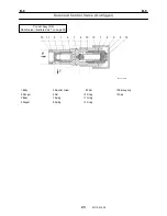
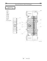
Rotary Joint
29
W181-0440E
Pneumatic section
Tightening torque
Sign / port
Thread size
N-m ft-lbf
Upper
Rc3/8
49 - 69
36 - 51
A1 Air
supply
Lower
G1/4
29.4 22
Upper
Rc3/8
49 - 69
36 - 51
A2
Service brake (primary)
Lower
G1/4
29.4 22
Upper
Rc3/8
49 - 69
36 - 51
A3
Service brake (secondary)
Lower
G1/4
29.4 22
L.L.C. section
Tightening torque
Sign / port
Thread size
N-m ft-lbf
Upper
W1 Heater
(IN)
Lower
Rc3/8
49 - 69
36 - 51
Upper
W2 Heater
(OUT)
Lower
Rc3/8
49 - 69
36 - 51
Attention
(*1): Face the "
・
" mark toward FRONT.
(*2): Apply water-proof sealant equivalent to THREE
BOND 4101. Do not apply grease.
(*3): Apply thread locking agent equivalent to
THREE BOND 1401 to lock the threads.
(*4): Apply grease (EP2) when attaching.
(*5): Do not use an organic solvent.
(*6): Do not remove the shaft (8) from the core (7). It
is press-fit within the core.
(*7): To prevent rust, apply grease (EP2) when
assembling.
(*8): Tapped hole (2 places) for slinging. The
applicable thread size is M10.
(*9): The "
・
" marks must be directed as shown in the
figure.
(*10): Do not use an organic solvent. The grease
grooves must be directed as shown below.
Summary of Contents for TR-800XXL4
Page 47: ...B 9 B 9 Rotary Joint 27 W181 0440E Upper view A Lower view B...
Page 119: ...F 1 F 1 Winch System 1 WF02 0251E F 1 Winch System 1 General Hydraulic Circuit for Winch...
Page 135: ...G 1 G 1 Telescoping System 3 WG02 0321E Telescoping cylinder at select...
Page 143: ...G 2 G 2 Boom Five Section Boom G 2 11 W536 0761E 11...
Page 196: ...13 13 W701 0220E K 2 K 2 Air Conditioner K 2 4 Layout 4 1 Overall layout 4 345 107 61000...
Page 197: ...14 14 W701 0220E K 2 K 2 Air Conditioner K 2 4 2 Overall layout 0 345 110 73000...
Page 198: ...15 15 W701 0220E K 2 K 2 Air Conditioner K 2 4 3 Evaporator section 5 345 107 02000...
Page 199: ...16 W701 0220E K 2 K 2 Air Conditioner 5 Compressor Assy...
Page 200: ...17 17 W701 0220E K 2 K 2 Air Conditioner K 2 6 Evaporator Assy...
Page 201: ...18 18 W701 0220E K 2 K 2 Air Conditioner K 2 7 Condenser Assy...
Page 202: ...19 19 W701 0220E K 2 K 2 Air Conditioner K 2 8 Electric 8 1 Electric circuit 0 363 205 60030...
Page 203: ...20 20 W701 0220E K 2 K 2 Air Conditioner K 2 8 2 Main harness A...
Page 204: ...21 21 W701 0220E K 2 K 2 Air Conditioner K 2 8 3 Main harness B...
Page 222: ...39 K 2 K 2 K 2 Air Conditioner 39 W701 0220E 12 2Compressor diagnosis chart 1 2...
Page 223: ...40 K 2 K 2 K 2 Air Conditioner 40 W701 0220E Compressor diagnosis chart 2 2...
Page 224: ...K 2 K 2 Air Conditioner 41 W701 0220E 13 Troubleshooting...
Page 225: ...K 2 K 2 Air Conditioner 42 W701 0220E...
Page 226: ...K 2 K 2 Air Conditioner 43 W701 0220E...
Page 227: ...K 2 K 2 Air Conditioner 44 W701 0220E...
Page 228: ...K 2 K 2 Air Conditioner 45 W701 0220E...
Page 229: ...K 2 K 2 Air Conditioner 46 W701 0220E...
Page 237: ...L 1 L 1 Control System 2 WL02 0090E 2 General of pneumatic control devices Pneumatic Circuit...
Page 291: ...T 5 T 5 Air Dryer 26 W232 0032E Heater View A 39 C B B A 58 59 2 IW232 0030E03...
Page 370: ...8 8 WZ03 3300E Z 5 Z 5 Electric Circuit MDT Carrier Upper Z 5 IWZ03 3300E01...
Page 372: ...10 Z 6 Z 6 Electric Circuit MDT Carrier Lower Z 6 10 WZ03 3310E IWZ03 3310E01...
Page 400: ...38 Z 24 Z 24 Harness Lower Sub 38 WZ04 2450E Z 24 Z 24 Harness Lower Sub 2 349 310 00200...


