T G W S IP -F X S /F S O G a te w a y S e rie s
User Manual
Tadiran Telecom
9
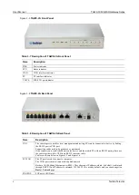
TGW16-2G Front Panel
Figure 1-7
Table 1-11
Description of TGW16-2G Front Panel
Item
Description
Three interface slots; each can correspond with four RJ45 sockets; each RJ45socket can
correspond with four pairs of analog lines.
Note: Numbers of interface slots vary from different configuration.
Matrix of 4 x 4 LED status indicators on interface card.
Each RJ45 socket has 8 pins leading out 4 pairs of analog telephone or trunk lines in agreement with the
pair specifications for Ethernet interfaces, whose corresponding relations can be seen in the table below.
CAT-5 cables are used to connect the interface card and distribution panel in equipment installation.
Standard RJ11 telephone lines can be used to plug in a RJ45 socket. The telephone/trunk lines are
connected to the 3
rd
pair of pins for simple call test.
Table 1-12
Pin Specifications for
TGW16/24-2G
RJ45 Socket Port
RJ45 Pin Number
1
2
3
4
5
6
7
8
Analog line pair
1
st
Pair
2
nd
Pair
3
rd
Pair
2
nd
Pair
4
th
Pair
TIP1
RING1
TIP2
TIP3
RING3
RING2
TIP4
RING4
Reference color
Orange
white
Orange
Green
white
Blue
Blue
white
Green
Brown
white
Brown
Summary of Contents for aeonix TGW4
Page 15: ...Tadiran Telecom xv...
Page 16: ......
Page 133: ...T G W S IP F X S F S O G a te w a y S e rie s User Manual Tadiran Telecom 117...


