T G W S IP -F X S /F S O G a te w a y S e rie s
User Manual
Tadiran Telecom
19
Table 1-30
Configuration Combination of TGW96-2G
M o d e ls
N u m b e r o f F X S
P o rts
N u m b e r o f F X O P o rts
C o n c u rre n t c a lls
TGW96-24-2G-C
TGW96-24-2G-2AC-C
TGW96-24-2G-2DC-C
Depend on the models and number of the interface cards.
24
TGW96-96-2G-C
TGW96-96-2G-2AC-C
TGW96-96-2G-2DC-C
96
TGW96-2G
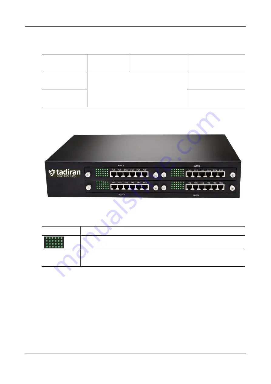
Front Panel
Figure 1-18
Table 1-31
Description of
TGW96-2G
Front Panel
Item
Description
Matrix of 6x4 LED status indicator on interface card
SLOT1~4
Four interface slots; each can contain one 24-port interface card.
Note: The interface card is hot swappable, but you should reboot the device after the
replacement of the interface card!
Numbering definition of system interface slots: on the low-left side of chassis is #1 slot (marked with
No.1 to 24), on the low-right side of chassis is #2 slot (marked with No.25 to 48), on the up-left side of
chassis is #3 slot (marked with No.49 to 72), and on the up-right side of chassis is #4 slot (marked with
No.73 to 96).
Each RJ45 socket has 8 pins leading out 4 pairs of analog telephone or trunk lines in agreement with the
pair specifications for Ethernet interfaces, whose corresponding relations can be seen in the table below.
CAT-5 cables are used to connect the interface card and distribution panel in equipment installation.
Standard RJ11 telephone lines can be used to plug in a RJ45 socket. The telephone/trunk lines are
connected to the 3
rd
pair of pins for simple call test.
Summary of Contents for aeonix TGW4
Page 15: ...Tadiran Telecom xv...
Page 16: ......
Page 133: ...T G W S IP F X S F S O G a te w a y S e rie s User Manual Tadiran Telecom 117...


