6-18
Cabinet Descriptions
Coral FlexiCom 6000 Installation Manual
Cabinet Descrip
tion
s
6
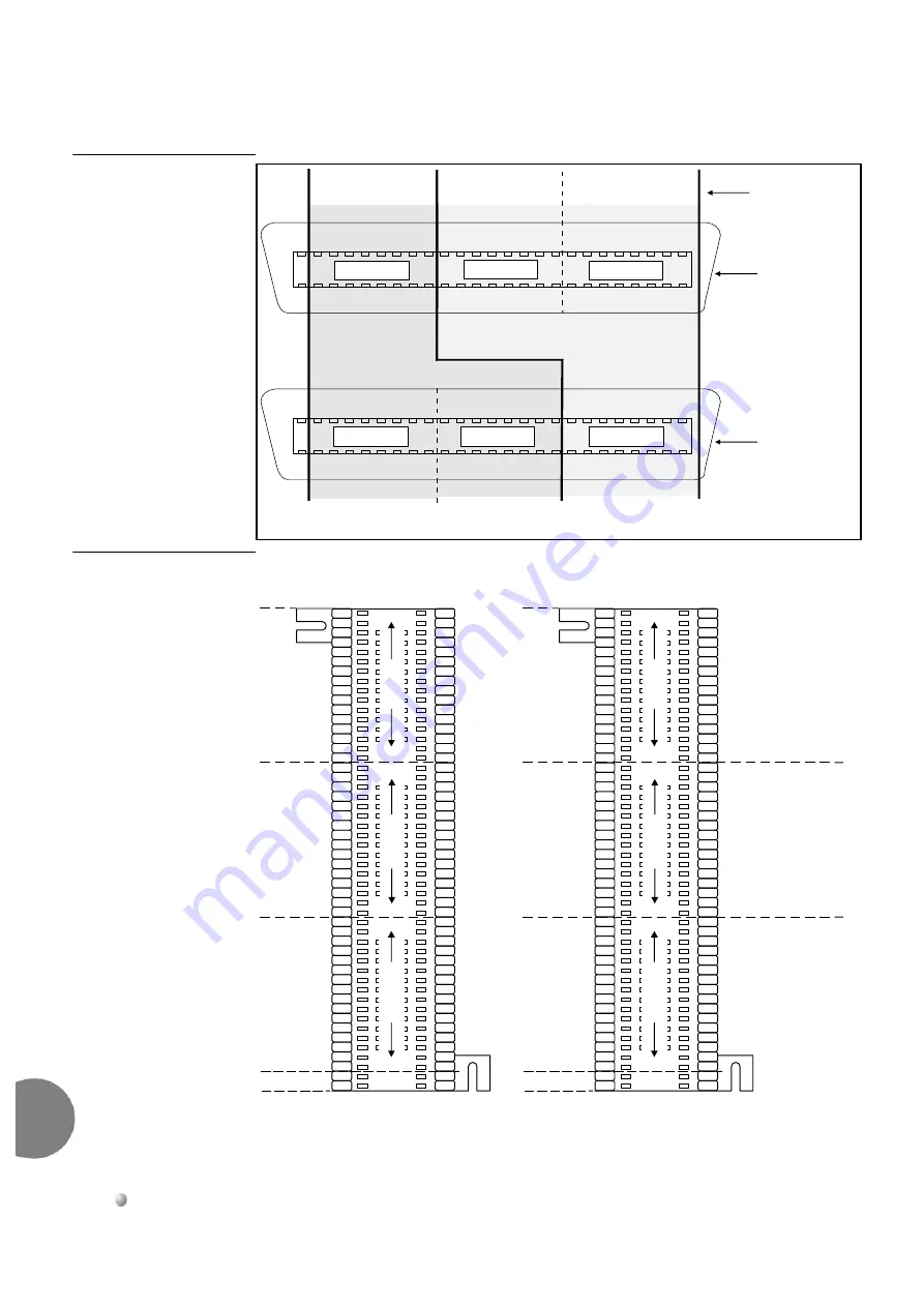
Figure 6-14
Connector
Pair Allocation
Figure 6-15
Connection
Layout for 66 Type Punch
Blocks
Pairs
9/34-16/41
Pairs
1/26-8/33
Pairs
17/42-24/49
Pair
25/50
25
34
26
9
1
25
50
50
NOT
USED
EVEN SLOTS
4,6,8,10,12,14,16,18
ODD SLOTS
3,5,7,9,11,13,15,17
ports 0-7
ports 0-7
ports 16-23
ports 16-23
ports 8-15
ports 8-15
Connector
Pins
LOWER
CONNECTOR
UPPER
CONNECTOR
17
1
42
26
9
34
42
17
Coral FlexiCom 5000, 6000
Pair 25
Not used
EVEN SLOTS
Ports 16-23
EVEN SLOTS
Ports 8-15
ODD SLOTS
Ports 8-15
Wht/Blu
Pa
ir
s 1
-8
Pa
irs
9
-16
Red/Grn
Red/Brn
Ylw/Blu
Ylw/Org
Vio/Brn
Pa
irs 1
7
-2
4
Pair 25
Not used
EVEN SLOTS
Ports 0-7
EVEN SLOTS
Ports 16-23
ODD SLOTS
Ports 0-7
Wht/Blu
Pa
ir
s 1
-8
Pa
irs
9
-16
Red/Grn
Red/Brn
Ylw/Blu
Ylw/Org
Vio/Brn
Pa
irs 1
7
-2
4
1/26
2/27
3/28
4/29
5/30
6/31
7/32
8/33
9/34
10/35
11/36
12/37
13/38
14/39
15/40
16/41
17/42
18/43
19/44
20/45
21/46
22/47
23/48
24/49
25/50
White/blue
White/orange
White/green
White/brown
White/slate
Red/blue
Red/orange
Red/green
Red/brown
Red/slate
Black/blue
Black/orange
Black/green
Black/brown
Black/slate
Yellow/blue
Yellow/orange
Yellow/green
Yellow/brown
Yellow/slate
Violet/blue
Violet/orange
Violet/green
Violet/brown
Violet/slate
UPPER I/O
CONNECTOR
LOWER I/O
CONNECTOR
Coral FlexiCom 5000, 6000


