Coral FlexiCom 6000 Installation Manual
Hardware Installation Procedure
2-15
Eq
uipment Insta
llation
2
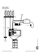
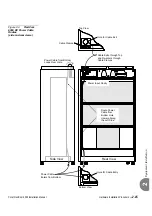
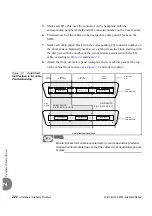
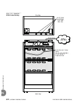
Figure 2-4
FlexiCom
6000 DC Power Cable
Routes
(side and rear views)
Side View
Cable Exits through Top
and Re-enters through
Cable Clamps
Power Cable
Enters from Bottom
Power Cable from Bottom
Loops Over Here
Cable Clamps
Hole for Cable Exit
Route Power
Cable from
Bottom Hole
Upward Along
the Left Side
Top View
Bottom View
Rear View
Hole for Cable Entry
Power Input Cavity


