6-16
Cabinet Descriptions
Coral FlexiCom 6000 Installation Manual
Cabinet Descrip
tion
s
6
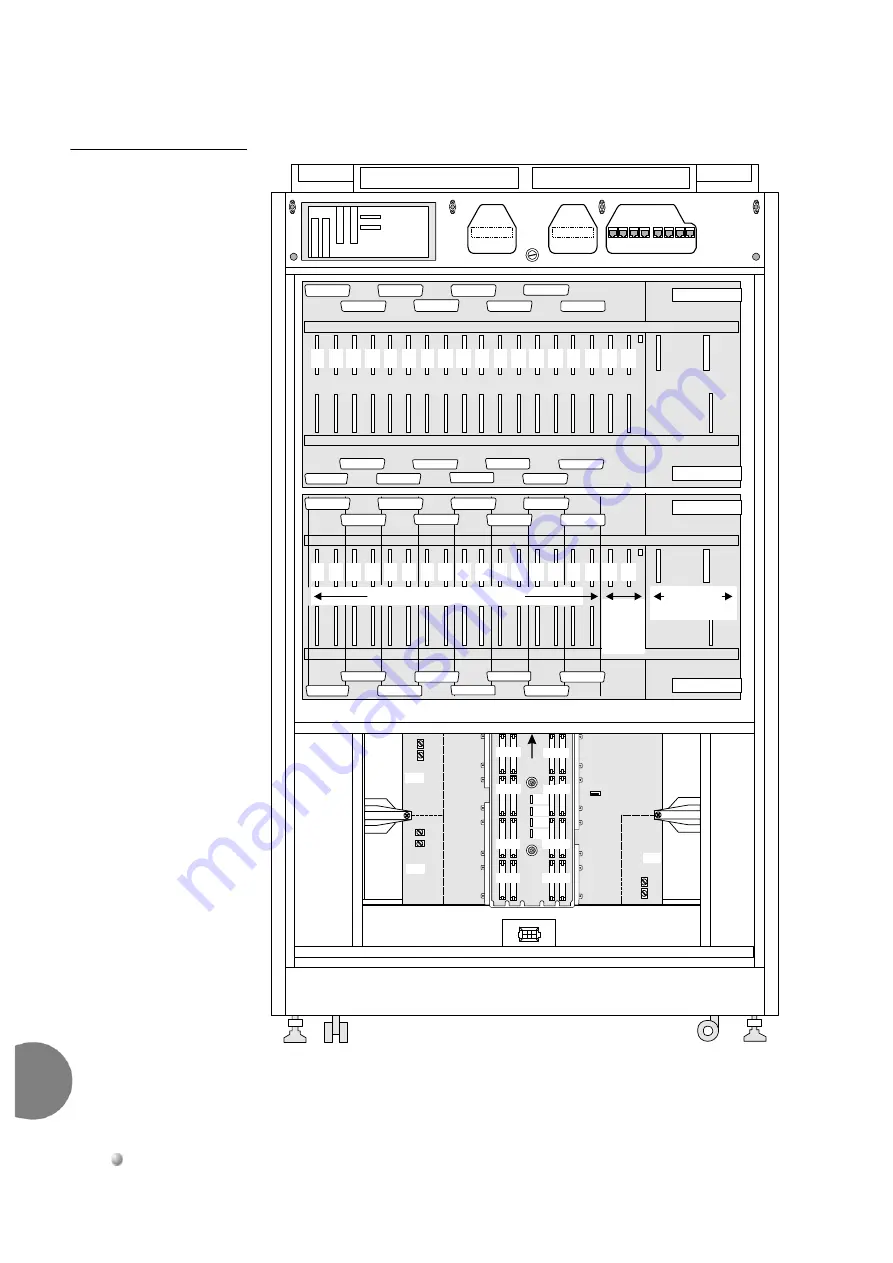
Figure 6-13
Coral
FlexiCom 6000-
Backplane Slot Diagram -
Rear View
Co
mmo
n C
o
ntrol
She
lf
U
PPE
R
Pe
riph
eral
Sh
el
f
1
2
3
4
5
6
7
8
9
10
11
12
13
14
15
16
17
18
UNIVERSAL I/O SLOTS
SH
AR
ED
SE
R
V
IC
E
SL
O
T
S
RPS
PPS
POWER
SUPPLIES
1
2
3
4
5
6
7
8
9
10
11
12
13
14
15
16
17
18
RPS
PPS
PP
S
PP
S
LO
WE
R Peri
ph
eral
Sh
el
f
J51
J49
J47
J43
J39
J37
J41
J45
J52
J50
J48
J44
J40
J46
J38
J42
J51
J49
J47
J43
J39
J45
J37
J41
J52
J50
J48
J44
J40
J46
J38
J42
UP
J5
J7
J2
J6
J8
J1
MPG-ATS
P9
P7 P8
P10
P11
P12
P6
P5
P13
P14
P4
P3
P20
P19
P18
P17
P15
P16
P2
P1
PS3
PS2
PS1


