Coral FlexiCom 6000 Installation Manual
Cabinet Descriptions
6-35
Cabinet Descrip
tion
s
6
Synchronization Connection Pins
The pin connections for each of the synchronization connections are especially
designed for longer life. Each pin connection is made up of four actual pins, divided
functionally into two pairs. The cable attaches to either the first and the third pins or
the second and fourth pins. If one of these delicate pins is damaged, the other pair
remains functional.
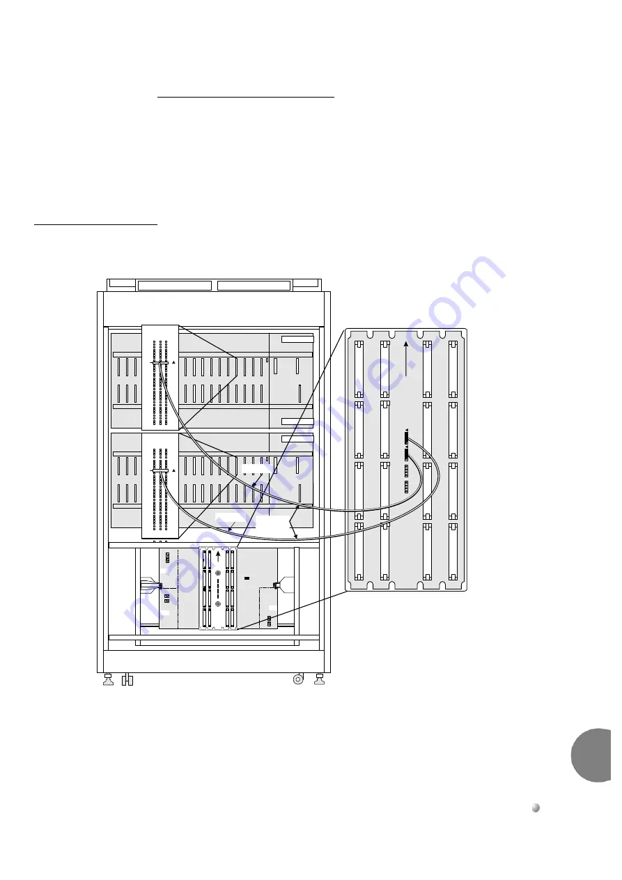
Figure 6-25
Synchronization Cabling
UP
J5
J7
J2
J6
J8
J1
MPG-ATS
PS3
PS2
PS1
C32
Pin
9
9
10
5
C1
15
20
25
30
J7
(from slot 4)
J7
J7
C32
9
10
5
C1
15
20
25
30
H-43 cable
UP
MPG-ATS
P7
P5
P3
P1
P10
P12
P14
P16
P8
P6
P4
P2
P11
P13
P15
P9
P20
P19
P18
P17
SEC SYNC
PRM SYNC
J7
(from slot 4)
Pin
9
Th
ird
Se
c.
Pr
m
.
Fo
u
rth


