background image

6

missprints and technical changes reserved

Instruction & Operating Manual

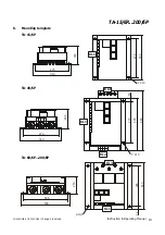
TA-15/6P...200/6P

11)

Current limit: In order to check the current limit the field must be disconnected, the motor must be

blocked and the field control (jumper 

XI

) must be jumpered. Switch on drive and preselect speed

and adjust the requested current with P5 (current limit). The red LED 6 (current limit) must light up.

This adjustment should be performed with in 10 sec., otherwise the blocking control will become

effective. If the adjustment takes longer than 10 sec. and the bolcking control is actuated, press the

key TA to confirm the blocking. The drive will then immidiately operate at the current limit.

12)

Zero-speed control: If a controlled deceleration after normal switch-off (provided the machine

operates with positive torque) is required, jumper 

VI

 must be installed to make the zero speed

control operative. (zero speed control is effective above approximately 10% of the speed.)

13)

Stability potentiometer P8. This potentiometer must be adjusted so that the drive operates without

overshoot in the presset speeds.

5.2 Tachometer feedback control:

1)

Check all connections with an Ohm-meter for grounds

2)

Install required jumpers for tachometer feedback control (depending if a.c. or d.c. tachometer is

used (see page 2) terminals 19 and 20 or 11 and 20 respectively.

3)

Remove resistor R82 and also remove jumpers 

VII

 and 

I

 . The electronic circuit is now without any

potential.

4)

For all further adjustments refer to the adjustments as previously described for the armature

feedback control, however, 

I x R compensation (P3) must be set fully counter clockwise.

6.

Troubleshooting

For fast and effective troubleshooting and for the location of defective components proceed as follows.
Check the drive for:
a) Intermittent or loose connections
b) Defective insulation of the connection leads
c) Defective motor (brushes etc.)

Caution!

Do not use 

any

 Mega-Ohm-meter, buzzer or similar test instruments.

Test instruments must be galvanically seperated from a.c. line. The electronic circuit

carries a voltage potential against ground when the drive is armature feedback

controlled (UA-controlled).

Summary of Contents for TA-15/6P

Page 1: ...ntriebstechnik de TA_BA TA 15 200_6P_EN PDF The German text applies in cases of doubt TA 15 6P 200 6P Instruction and Operation Manual Caution There is always a risk involved in the handling of electr...

Page 2: ...al 4 and 9 Jog Speed ON Closing contact Drive remains switched on until contacts open 1 Technical Data r Motor Zero Speed Indicator r Current Limit control r Tachometer Signal control r Electronic cir...

Page 3: ...or speed r When tachometer feedback is utilized jumpers I and VII and resistor R82 must be removed r Jumpers IX and X must be installed and jumper VIII must be removed r The adaption of the tachometer...

Page 4: ...installed or when the reference speed is changed Current limit P5 Adjustment of the requested max armature current adjust the nominal motor current Minimum Speed P6 Adjustment of min speed during ope...

Page 5: ...center position Potentiometer P3 IxR Compensation set fully counter clockwise Potentiometer P8 Stability set in center position Potentiometer P7 Jog speed set fully counter clockwise Potentiometer P1...

Page 6: ...iometer P8 This potentiometer must be adjusted so that the drive operates without overshoot in the presset speeds 5 2 Tachometer feedback control 1 Check all connections with an Ohm meter for grounds...

Page 7: ...tive fuse Si 1 on the upper PC board c LED 8 Power on does not light up d LED 9 does not light up however LED 11 lights up jumper or quick stop contacts terminals 24 and 25 not closed e No reference v...

Page 8: ...Type TA 15 6P 200 6P a Too low adjustment of current limit b Motor is overloaded mechanical defect on machine or motor Check motor brushess c Supply voltage 15V for electronic circuit incorrect or mi...

Page 9: ...VITESSE D ACCROCHAGE Reglerfreigabe ALTERNATIF FIELD DC TACHOMETER Sollwertpotentiometer Schleichgang JOG SPEED DEBLOCAGE RUN EXCITATION Feld Anker Netz INDUIT ARMATURE ALIMENTATION EN LINE FAULT DOC...

Page 10: ...changes reserved Instruction Operating Manual TA 15 6P 200 6P 8 Mounting template TA 40 6P TA 60 6P 200 6P TA 15 6P 310 270 165 7 x 13 270 350 KL1 310 270 165 7 x 13 400 270 460 40 KL3 KL1 KL2 530 486...

Reviews: