Instruction and Operating Manual
TA-U1...U280
Misprints and technical changes reserved
36
5.1.7 Braking Unit
Connection between braking chopper, braking resistor and regulator are a source of radiated and conducted interfe-
rence. The cable should be screened and as short as possible. Ensure proper grounding (Chapter 4.1.3).
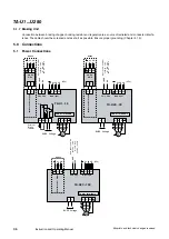
5.0 Connections
5.1 Power Connections
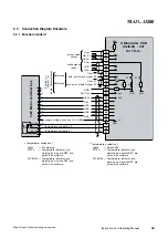
L1 L2 L3
L1 L2
L+ L-
+24V
0V
L3
(3Ph)
Power terminals
Main input
1+ 1-
1+ 1-
External
P
ower
Supply
L1 L2
L1 L2
UD_EX
P-S-C
U
W
M
u
v
w
V
BUSS Voltage
R2
R1
+ -
External
Brake
resistor
R
TA-U1...15
B+
B-
input
power
amplifier
opening
/
stop
for
safe
stop
24V
DC
/
30mA
Option
10A
10A
Safe Stop
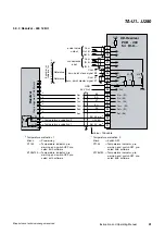
L1 L2 L3
L1 L2
L+ L-
+24V
0V
L3
(3Ph)
Power terminals
Main input
U
W
M
u
v
w
V
BUSS Voltage
+ -
TA-U22...30
Safe Stop
Input
power
amplifier
opening
/
stop
for
safe
stop
24V
DC
/
30mA
1+ 1-
1+ 1-
External
P
ower
Supply
L1 L2
L1 L2
UD_EX
P-S-C
Option
10A
10A
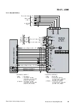
L1 L2 L3
L1 L2
L+ L-
+24V
0V
L3
(3Ph)
Power terminals
Main input
U
W
M
u
v
w
V
BUSS Voltage
+ -
TA-U37...150
Safe Stop
Input
power
amplifier
opening
/
stop
for
safe
stop
24V
DC
/
30mA
External
P
ower
Supply
L1 L2
Option
10A
10A
1L11L2


