TA-U1...U280
Instruction and Operating Manual
Misprints and technical changes reserved
39
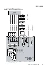
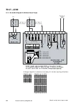
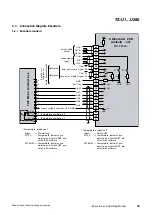
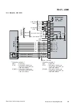
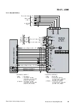
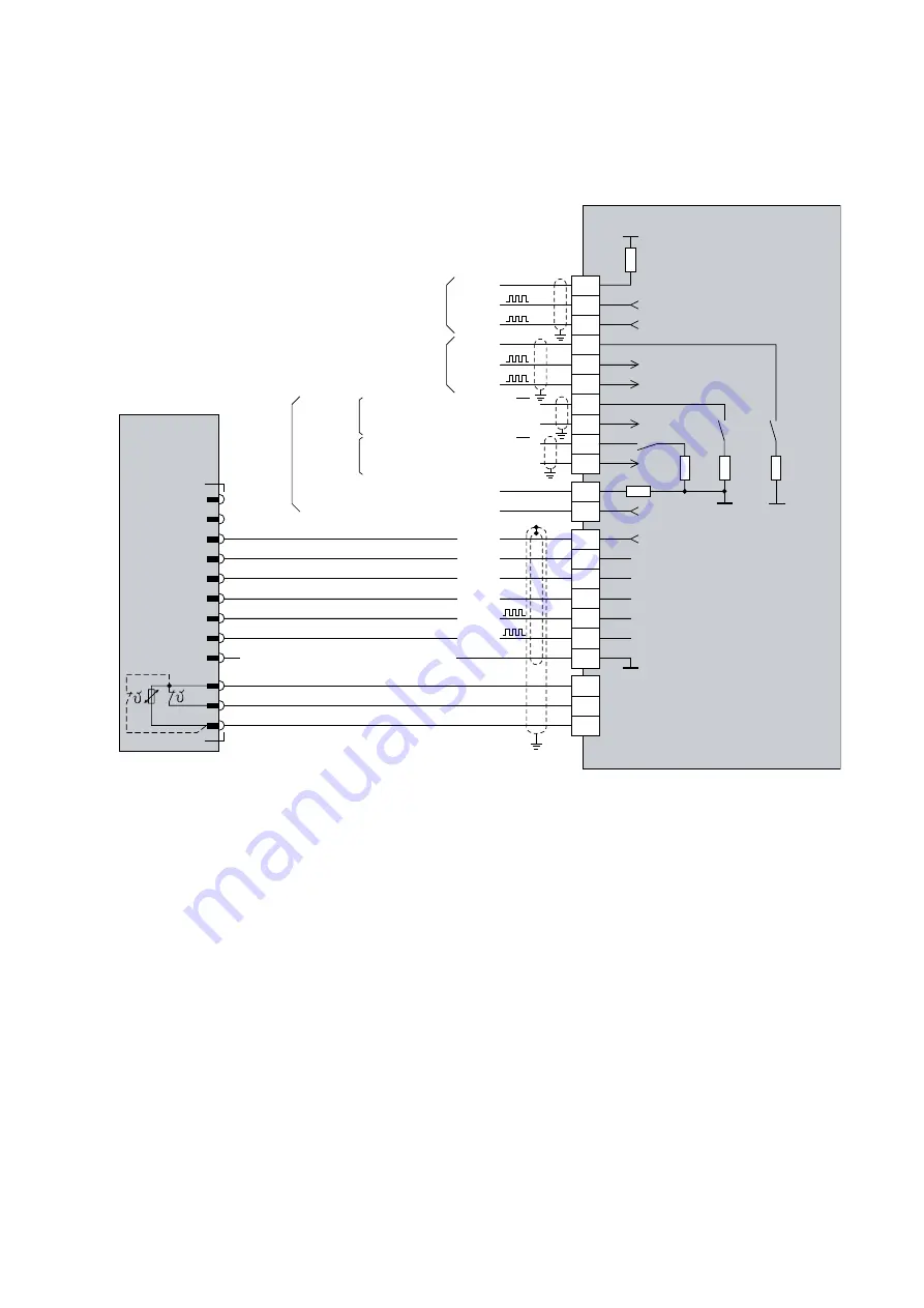
5.3 Connection Diagram Encoders
5.3.1 Encoder standard
37
36
35
34
32
31
30
29
28
27
26
25
24
23
22
21
0V
33
P1
P3
P2
supply voltage encoder +0V GND
HS2
HS3
HS1
38
39
40
41
42
HS4
HS5
+6,5V
24V Out
GND
zero point master signal Z1
UD-Encoder PCB
(default) - 401
for TA-U...
TA
E
Motor
terminal
box
GND
*)
Temperature evaluation 1
*)
Temperature evaluation 2
Klixon
= Switch-OFF
PT100
= Temperature indicator, pre-
warning and switch-OFF pre-
seted with software
KTY84130 = Temperature indicator, pre-
warning and switch-OFF pre-
seted with software
Klixon
= Pre-warning
PT100
= Temperature indicator, pre-
warning and switch-OFF pre-
seted with software
KTY84130 = Temperature indicator, pre-
warning and switch-OFF pre-
seted with software
B
S1-1
GND
GND
GND
A
+24V
+6,5V
B
A
Z2
Z1
S1-2
S1-3
10R
10R
10R
10R
10R
Out A
Out B
Com
actual value
output
IN A
IN B
Com
conductance
input
Encoder
or
Initiators
for
angle
Synchronization
Reference
Reference
Temperature evaluation 1
Temperature evaluation 2
8
7
9
12
10
11
6
5
4
3
2
1
BK
VT
WH
GY
GN
BU
PK
YE
BN
RD
zero point slave signal Z2
Com Z1
Com Z2
RD
WH


