Instruction and Operating Manual
TA-U1...U280
Misprints and technical changes reserved
50
7.2 Troubleshooting
7.2.1 Sensor test
The five LED indicators U, V, W, A, B (pale) indicate a proper working of the sensors from the motor.
U / V / W
- Position sensors
A / B
- Speed sensors
To check the hall-sensors, you have to proceed as follows:
a) Disconnect device from mains.
b) Connect control cables to motor.
c) Remove power cables of motor on terminals U, V, W on the regulator.
d) Turn on mains and control voltage and carry out after the operationally following test.
e) Turn the motor shaft slowly counterclockwise with your hand (look at output shaft). The LED indicators U, V, W, A,
B start to light on and off in a definite order. (refer to diagram below).
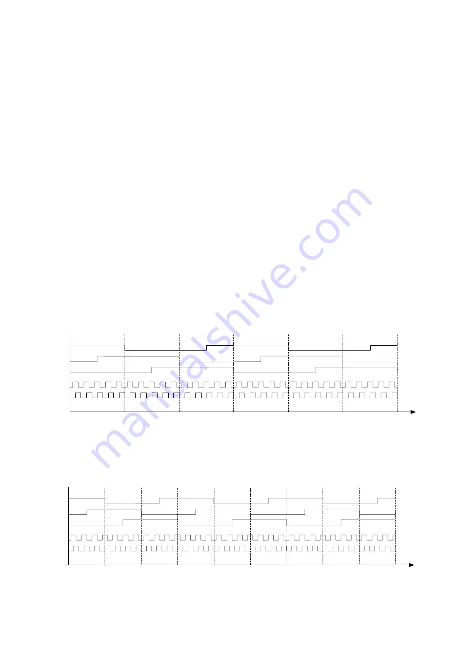
Diagramm: light-intervals (ideal diagram)
Correspond to light-intervals diagramm, the sensors and motor control cable works properly
4-pole motor: BL-71...BL-160
with incremental encoder with 30 pulses/360° scale 0-360°
6-pole motor: BL-N-71...BL-N-100
with incremental encoder with 30 pulses/360° scale 0-360°
8-pole motor: BL-180...BL-315 and BL-N-112...BL-N-180 with incremental encoder with 60 pulses/360° scale 0-180°
Diagramm light-intervals 4- and 8-pole motors
Diagramm light-intervals 6-pole motors
A
B
0°
120°
(60°)
60°
(30°)
180°
(90°)
240°
(120°)
300°
(150°)
360°
(180°)
W
V
U
1 motor revolution 4-pole motor
(1/2 motor revolution 8-pole motor)
LED On
LED Off
A
B
0°
120°
160°
40°
80°
200°
240°
280°
320°
360°
W
V
U
1 motor revolution 6-pole motor
LED On
LED Off

