background image

PCP-1500/2000

A

/

2000/

5000 Series 

  Rev 3 

2023/01/16 

10/52 

Copyright © 2023 by TAEHA CORP. All Rights Reserved


2.5


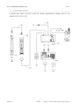
PCP standard system 

A standard type means a structure in which the material suppliers(barrel, cartridge, tank, etc.) are 
separated from the Pro-Pump. 

Summary of Contents for PCP-1500 Series

Page 1: ...PRO PUMP SYSTEM PCP 1500 2000A 2000 5000 Series User manual...

Page 2: ...pump controller 8 2 5 PCP standard system 10 2 6 PCP module system PCPM 12 3 Names of each part 14 4 Operation 15 4 1 Precautions on use and assembly 15 4 1 1 In connection Stator A and Rotor B 15 4 1...

Page 3: ...s Reserved 5 3 Assembly of PCP 2000 5000 41 6 PCP 1500 2000A 2000 5000 Part list 45 6 1 PCP 1500 Part list 45 6 2 PCP 2000 Part List 46 6 3 PCP 2000A Part List 47 6 4 PCP 5000 Part List 48 7 Maintenan...

Page 4: ...rate agreement and the following cases the warranty period will be one year in the event of defects Following 1 In case you modify the equipment without permission by Taeha Corp 2 If someone other tha...

Page 5: ...Please read this manual to get the most out of your product and do what you want 2 2 Feature Precise and Consistent volume of fluid is dispensed even when environmental factors affect viscosity and pr...

Page 6: ...PCP 1500 2000A 2000 5000 Series Rev 3 2023 01 16 6 52 Copyright 2023 by TAEHA CORP All Rights Reserved 2 3 Dimension and specification...

Page 7: ...60 558 x 60 x 60 Weight 2 0kg 2 0kg 5 0kg 5 0kg Input Pressure 0 0 6MPa Max Dosing Pressure 2 0MPa 2 5MPa 2 0MPa Viscosity cPs 0 500 000 Dosing Volume Rev 1 8mL 2mL 2 2mL 5 5mL Recommended motor spee...

Page 8: ...PCP 1500 2000A 2000 5000 Series Rev 3 2023 01 16 8 52 Copyright 2023 by TAEHA CORP All Rights Reserved 2 4 Features and specification of Pro pump controller...

Page 9: ...f cm2 Air In Port One Touch Fitting PC 6 Max 0 7MPa Air Hose Air Out Port One Touch Fitting PC 6 Max 0 7MPa Input signal Contact input or NPN open collector Shot end signal NPN open collector Dosing C...

Page 10: ...eries Rev 3 2023 01 16 10 52 Copyright 2023 by TAEHA CORP All Rights Reserved 2 5 PCP standard system A standard type means a structure in which the material suppliers barrel cartridge tank etc are se...

Page 11: ...es 1 Set 2 Pro Pump Controller Procon 1000 1 Set Pro Pump 1K Pump Controller 3 Motor Cable 1 Pc Length 1 5m Motor Cable 4 Air Tube Ass y 6 Auto Jointer 1 Pcs Length 1 5m Air Hose 5 Foot Switch 1 Pc Le...

Page 12: ...0 5000 Series Rev 3 2023 01 16 12 52 Copyright 2023 by TAEHA CORP All Rights Reserved 2 6 PCP module system PCPM Module type means that the material supplier barrel cartridge tank etc is integral with...

Page 13: ...material supply part module type 2 Pro Pump Controller Procon 1000 1 Set Pro Pump 1K Pump Controller 3 Motor Cable 1 Pc Length 1 5m Motor Cable 4 Air Tube Ass y 6 Auto Jointer 2 Pcs Length 1 5m Air H...

Page 14: ...PCP 1500 2000A 2000 5000 Series Rev 3 2023 01 16 14 52 Copyright 2023 by TAEHA CORP All Rights Reserved 3 Names of each part...

Page 15: ...se direction Do not activate the pump without applying the material to the stator If so even for a short duration of time there might be a damage on the stator 4 1 2 Eliminating bubbles before liquid...

Page 16: ...as clean air at least 5kgf cm2 Please piping so that the air piping of the material supply system is not twisted or folded 2 Please connect foot switch or external device to the control terminal 3 Pow...

Page 17: ...clockwise to fully lock it Please clean the residual liquid 7 Set the dispensing speed to approximately 10 by switching to the steady mode then press the shot button to check if it dispenses without...

Page 18: ...uck back time suck back speed to an appropriate value Excessive suck back setting may cause backflow of mixed liquid into the pump and cause malfunction 4 Set the appropriate shot time by setting the...

Page 19: ...creen are set to the determined values Periodically check if there is a change in the shot volume 2 Start the operation by selecting it that matches the dispense mode 3 After finishing work remove nee...

Page 20: ...52 Copyright 2023 by TAEHA CORP All Rights Reserved 5 Disassemble 5 1 Disassembly of PCP 1500 2000A This section describes the procedure for disassembling the pro pump PCP 1500 2000A for its maintena...

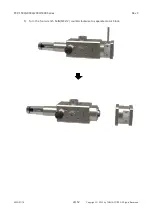
Page 21: ...PCP 1500 2000A 2000 5000 Series Rev 3 2023 01 16 21 52 Copyright 2023 by TAEHA CORP All Rights Reserved 2 Turn the four wrench bolts M3x12 counterclockwise to separate the motor...

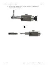
Page 22: ...PCP 1500 2000A 2000 5000 Series Rev 3 2023 01 16 22 52 Copyright 2023 by TAEHA CORP All Rights Reserved 3 Use a spanner to separate the outlet adapter...

Page 23: ...PCP 1500 2000A 2000 5000 Series Rev 3 2023 01 16 23 52 Copyright 2023 by TAEHA CORP All Rights Reserved 4 Turn the four wrench bolts M4x8 counterclockwise to separate stator cap...

Page 24: ...PCP 1500 2000A 2000 5000 Series Rev 3 2023 01 16 24 52 Copyright 2023 by TAEHA CORP All Rights Reserved 5 Turn the four wrench bolts M3x12 counterclockwise to separate motor block...

Page 25: ...000A 2000 5000 Series Rev 3 2023 01 16 25 52 Copyright 2023 by TAEHA CORP All Rights Reserved 6 Fix one side with the repair tool use a dedicated spanner to slowly rotate stator counterclockwise to se...

Page 26: ...PCP 1500 2000A 2000 5000 Series Rev 3 2023 01 16 26 52 Copyright 2023 by TAEHA CORP All Rights Reserved 7 Use a spanner to separate the chamber cap...

Page 27: ...1500 2000A 2000 5000 Series Rev 3 2023 01 16 27 52 Copyright 2023 by TAEHA CORP All Rights Reserved 8 Separate chamber and rotor ass y 5 1 1 Disassembly of Rotor ass y and seal 1 Separate the joint sl...

Page 28: ...PCP 1500 2000A 2000 5000 Series Rev 3 2023 01 16 28 52 Copyright 2023 by TAEHA CORP All Rights Reserved 2 Hold the idle coupling with the spanner and turn bolt M4x8 counterclockwise to remove it...

Page 29: ...Rev 3 2023 01 16 29 52 Copyright 2023 by TAEHA CORP All Rights Reserved 3 Pull off the bearing block and seal housing 4 Separate the rotary seal and seal support in the rotor direction Assemble in th...

Page 30: ...01 16 30 52 Copyright 2023 by TAEHA CORP All Rights Reserved 5 2 Disassembly of PCP 2000 5000 This section describes the procedure for disassembling the Pro Pump PCP 2000 5000 for its maintenance 1 Pr...

Page 31: ...PCP 1500 2000A 2000 5000 Series Rev 3 2023 01 16 31 52 Copyright 2023 by TAEHA CORP All Rights Reserved 2 Turn the four wrench bolts M5x12 counterclockwise to separate motor...

Page 32: ...PCP 1500 2000A 2000 5000 Series Rev 3 2023 01 16 32 52 Copyright 2023 by TAEHA CORP All Rights Reserved 3 Turn the bolts M3x5 counterclockwise to separate outlet adapter...

Page 33: ...PCP 1500 2000A 2000 5000 Series Rev 3 2023 01 16 33 52 Copyright 2023 by TAEHA CORP All Rights Reserved 4 Turn the four wrench bolts M4x10 counterclockwise to separate the stator cap and stator sleeve...

Page 34: ...PCP 1500 2000A 2000 5000 Series Rev 3 2023 01 16 34 52 Copyright 2023 by TAEHA CORP All Rights Reserved 5 Turn the four wrench bolts M4x15 counterclockwise to separate the motor block...

Page 35: ...000A 2000 5000 Series Rev 3 2023 01 16 35 52 Copyright 2023 by TAEHA CORP All Rights Reserved 6 Fix one side with the repair tool use a dedicated spanner to slowly rotate stator counterclockwise to se...

Page 36: ...PCP 1500 2000A 2000 5000 Series Rev 3 2023 01 16 36 52 Copyright 2023 by TAEHA CORP All Rights Reserved 7 Use a spanner to separate the chamber cap...

Page 37: ...2000 5000 Series Rev 3 2023 01 16 37 52 Copyright 2023 by TAEHA CORP All Rights Reserved 8 Hit the rotor with a rubber hammer and push it out in the direction of the chamber cap to remove the chamber...

Page 38: ...PCP 1500 2000A 2000 5000 Series Rev 3 2023 01 16 38 52 Copyright 2023 by TAEHA CORP All Rights Reserved 5 2 1 Disassembly of rotor ass y 1 Separate Joint coupling and tee key...

Page 39: ...ight 2023 by TAEHA CORP All Rights Reserved 2 Using two spanners one holds and fixes the D Cut part of the rotor assembly s rod Hold the idle coupling with the remaining spanner and turn it counterclo...

Page 40: ...Series Rev 3 2023 01 16 40 52 Copyright 2023 by TAEHA CORP All Rights Reserved 5 2 2 Disassembly of rotary seal After removing the material in the seal housing and rotary seal gaps with a cleaning so...

Page 41: ...d 5 3 Assembly of PCP 2000 5000 1 Insert the seal to be replaced into the driving shaft in the direction shown in the figure reverse assembly direction to increase the size of holes 2 Assemble in the...

Page 42: ...PCP 1500 2000A 2000 5000 Series Rev 3 2023 01 16 42 52 Copyright 2023 by TAEHA CORP All Rights Reserved 3 When assembling the seal block assemble with the open direction facing the rotor...

Page 43: ...ev 3 2023 01 16 43 52 Copyright 2023 by TAEHA CORP All Rights Reserved 4 Assemble the bearing block 5 Tighten the idle coupling to the end At this time make sure that the tee key homes match 6 Assembl...

Page 44: ...PCP 1500 2000A 2000 5000 Series Rev 3 2023 01 16 44 52 Copyright 2023 by TAEHA CORP All Rights Reserved...

Page 45: ...r 1 AL6061 18 101008 10 Coupling joint 1 Poly urethane 5 101008 20 A Inlet plug blank 1 AL6061 19 101008 84 Drive coupling 1 SUS303 6 101008 20 C Inlet module plug 1 AL6061 A Bolt M4x8 4 101008 20 D I...

Page 46: ...01010 84 Drive coupling 1 SUS303 6 101010 137 Heating blank 2 AL6061 A Bolt M3x5 3 7 101010 20 A Inlet plug blank 1 AL6061 B O Ring AS023 4 FKM 1472 8 101010 20 D Inlet plug T03 1 AL6061 C Bolt M3x4 3...

Page 47: ...08 10 Coupling joint 1 Poly urethane 5 101008 20 A Inlet plug blank 1 AL6061 19 101008 84 Drive coupling 1 SUS303 6 101008 20 C Inlet module plug 1 AL6061 A Bolt M4x8 4 101008 20 D Inlet circular plug...

Page 48: ...01010 84 Drive coupling 1 SUS303 6 101010 137 Heating blank 2 AL6061 A Bolt M3x5 3 7 101010 20 A Inlet plug blank 1 AL6061 B O Ring AS023 4 FKM 1472 8 101010 20 D Inlet plug T03 1 AL6061 C Bolt M3x4 3...

Page 49: ...r determined and periodic within a year inspections Danger Be sure to take necessary measures such as manual mode of the equipment emergency stop power off etc before performing maintenance and inspec...

Page 50: ...omena is as follows Alarms that may occur due to hardware protection or internal element breakage Alarms that may occur from incorrect settings when setting motion programs and points Alarms that may...

Page 51: ...ean to prevent so that the contamination by dust or solution does not interfere with the operation of the equipment Supplied Air Occasionally Check the piping connection joints or if there is no leaka...

Page 52: ...ck if there is a change in the tank air supply pressure 6 Check if there is a leak in the liquid connection fitting If there is a leak in nozzle end during the standby time after dispensing 1 Check if...

Reviews: