background image

E-mail  :  cutex@chol.com 


    http://www.cutex.kr 


-  2  -                             

▷ 

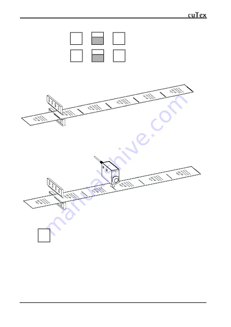
Set  function.(Sensor  cutting:  "1",  Normal  cutting  :  "0")


  Sensor  cutting  : 

FILE


⇒ 

1

EXTRA


⇒ 

SE T


  Normal  cutting  : 

FILE


⇒ 

0

LENGTH

CLEAR


⇒ 

SE T

▷ 

Locate  the  cutting  line  of  label  on  the  lower  knife  blade.

      (This  step  must  go  ahead  of  sensor  adjustment.)

▷ 

Sensor  Adjustment

      Light  sensor-beam  on  sensing  point  of  label.
      (Refer  to  "How  to  use  sensor  R58  EXPERT  of  next  page.)


▷ 

Press  START  button.


START


※ 

Check  Points  for  cutting  trouble

          -  Check  if  you  adjust  sensor  after  locating  cutting  line  of  label  on  the  knife  blade.
          -  Move  the  sensor  forwards  or  backwards.
          -  Check  sensitivity  &  height  of  the  sensor.
          -  Check  if  the  switch  is  upside  for  elastic,  downside  for  non-elastic  including  label.

Summary of Contents for cuTex TBC-50S

Page 1: ......

Page 2: ...ing length 70mm Cutting quantity 120 pcs Turn on the POWER SW Set cutting length 70mm Press the following buttons in order LENGTH 7 0 LENGTH CLEAR SET Button 0 has a double fuctions of 0 and eraising current length Set cutting quantity 120 pcs Q TY 1 EXTRA SPEED 2 0 LENGTH CLEAR SET ...

Page 3: ...head of sensor adjustment Sensor Adjustment Light sensor beam on sensing point of label Refer to How to use sensor R58 EXPERT of next page Press START button START Check Points for cutting trouble Check if you adjust sensor after locating cutting line of label on the knife blade Move the sensor forwards or backwards Check sensitivity height of the sensor Check if the switch is upside for elastic d...

Page 4: ...the jack of sensor into the connector of machine downside Locate the cutting line of label on the lower knife blade precisely move the sensor close to the knife This step is essential just before fix the location of sensor Adjust the sensor with guide control bolt for lightening the beam on the center of marking point ...

Page 5: ...on lamp delay L D will be off and Q T will stop blinking This time if Q T continues to blink quickly the contrast is insufficient Set it again Caution Whatever the background is darker or lighter than the mark activate TEACH the background first and the mark second After setting the sensor do not press Delay L D button it may happen an error changing input data In the case of objects with reflecti...

Page 6: ...meter or program 4 FEED 6 FEED to move the roller manually for mounting the material on the machine or for feeding it forwards or backwards SPEED 2 Speed up The current speed appears on the left upside of LCD display with Normal speed 50 Maximum speed 100 8 SPEED Speed up The current speed appears on the left upside of LCD display with Normal speed 50 Maximum speed 0 Speed up down is possible in a...

Page 7: ...re use please confirm the voltage and make ground earth connection Static electricity will be reduced to a half Do not access hands or any object close to the working knife for safety When the knife blade becomes dull please use it after grinding with the grinding machine Please do not let the unskilled person grind manually or install the knife blade EXCHANGE OF KNIFE First of all unscrew 4 bolts...

Page 8: ...ting test with paper or tissue by M CUT button right middle left of knife in order and adjust control bolt of upper knife finally If cutting is normal fasten the control bolts of upper knife firmly Attach removed stopper again Mount of roll Fix the roll triangle by 4mm wrench Exchange of fuse Take off the power plug and exchange as picture Cleaning of anti static brush If anti static function beco...

Page 9: ...E mail cutex chol com http www cutex kr 8 TBC 50S Part Drawing A Feeding part ...

Page 10: ...2 A 9 Slide Block of Upper Roller A 27 7 Clamping Bolt M4 4 A 10 Right Roller Bracket A 27 8 Stopper A 11 Slide Lever A 27 9 Spring Clamping Bolt A 12 Oilless A 27 10 Spring M4 15 A 13 Clamping Washer A 28 Lower Roller A 14 Wrench Bolt M 14L A 29 Upper Roller A 15 Tie Bar of Stepping Motor A 30 Front guide Pin A 16 Bearing Cover A 31 Lever Shaft A 17 Clamping Bolt M3 5L A 32 Guide Ring A 18 Feed t...

Page 11: ...E mail cutex chol com http www cutex kr 10 TBC 50S Part Drawing B Cutting part ...

Page 12: ...e Plate Left B 14 Lower Knife B 33 Pressure Spring B 15 Wrench Bolt M5 15L B 34 Clamping Bolt of Pressure Plate B 16 Motor Reduction Gear B 35 Urethane Bush B 17 Clamping Bolt M5 42L B 36 Tension control Washer B 18 Motor Supporter B 37 Tension control Nut B 19 Motor Key B 38 Tension control Bolt B 20 Ball Bearing 6004 B 39 Front Cover B 21 Snap Ring B 40 Clamping Bolt B 22 Crank Bundle B 41 Anti ...

Page 13: ...E mail cutex chol com http www cutex kr 12 TBC 50S Part Drawing C Other part ...

Page 14: ...cket C 43 Clamping Bolt M4 8L C 13 Rear Guide pin Bracket C 44 Sponge C 14 Wrench Bolt M4 15L C 45 Base C 15 Rear Tension guide Block C 46 Clamping Bolt M4 8L C 16 Detent Screw M4 6L C 47 Condenser C 17 Guide Ring C 48 Terminal C 18 Upper Guide Plate C 49 AC Connector OUT PUT C 19 Clamping Bolt M3 5L C 50 AC Connector IN PUT C 20 Micro Limit Switch C 51 Transformer C 21 Plate nut C 52 Clamping Bol...

Page 15: ...E mail cutex chol com http www cutex kr 14 ...

Page 16: ...ts before the cutting line of labels Label cutter S SH Move the sensor towards knife side as long as the difference by pushing 7 It cuts after the cutting line of labels Label cutter S SH Move the sensor towards counter knife side as long as the difference by pushing 8 ERROR on LCD LED ERROR CODE 064 Sensor check Er Label cutter S SH Trouble in Mark sensor Check if the sensor is connected well or ...

Reviews: