background image


                                                                                                            Operations Manual 


SV-100-M-DVR 

Part Number: 1008148 


Page 5 of 54 

Version 1.0. 08/18/2009


production/integration schedule.  TAG’s floor technicians are cross-trained in multiple 
disciplines so they can be redistributed to any cell that encounters production 
bottlenecks, which ensures optimal efficiency. 

2.2.3 

Lifecycle Management 

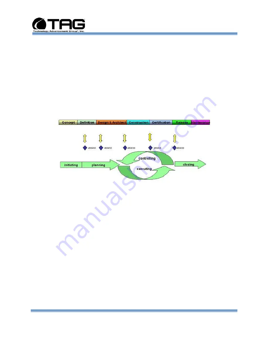
TAG’s world-class Program Management discipline models the renowned 
methodologies of the Project Management Institute (PMI) to ensure successful 
completion of the task at hand.  Our Program Managers (PMs) serve as the voice of the 
customer – driving requirements to which the rest of TAG’s organization answers.  As 
an explicit tenet of TAG’s corporate mission statement, the PMs not only track cost, 
schedule, and technical compliance throughout a project’s period of performance, but 
also ensure the customer is supported well beyond it. 


Summary of Contents for SV-100-M-DVR

Page 1: ...SV 100 M DVR Operations Manual TAG 22355 TAG Way Dulles VA 20166 ...

Page 2: ...rt to ensure the correctness and completeness of the material in this document TAG shall not be liable for errors contained herein The information in this document is subject to change without notice TAG makes no warranty of any kind with regard to this material including but not limited to the implied warranties of merchantability and fitness for a particular purpose 1 1 Trademarks All trademarks...

Page 3: ...Dulles Vi ng facility pr neer design actical comb O allow for r cost effectiv TD requirem rced throug s enables esses of the ed across va nces all cor e to consis g on the and leverag odel to ensu are exceede fecycles omers IT ation and rd in serve as a ensure risk y rely on the 100 M DVR 1 0 08 18 lifications f IT solution respected h Program Ma irginia TAG rovides all t n test man bat theater ra...

Page 4: ... t every step s ensuring on is comp ions are pru eering ver the past d in severa w TAG to te nsite to the rements of the MIL ST currently Lifecycle EMI test c also provide signed to su mbly lines hour system uction status with externa ty Assuran ction anufactur nufacturing cility to mini manufactur anufacturin of operating amline man 100 M DVR 1 0 08 18 es g upon Multi drive the sc D tools Co d di...

Page 5: ... TAG s world class Program Management discipline models the renowned methodologies of the Project Management Institute PMI to ensure successful completion of the task at hand Our Program Managers PMs serve as the voice of the customer driving requirements to which the rest of TAG s organization answers As an explicit tenet of TAG s corporate mission statement the PMs not only track cost schedule a...

Page 6: ...Operations Manual SV 100 M DVR Part Number 1008148 Page 6 of 54 Version 1 0 08 18 2009 Document Revision History Date Version Number Updated By Description of Changes 08 18 2009 1 0 Alan Huckerby Author ...

Page 7: ...ust All of our servers are based on the latest in Intel Core Duo and Pentium M technology Configuration options include extended memory and enhanced video optimization All of our products are backed by our world class lifecycle management and post sales support 3 1 1 Organization This manual is divided into the following chapters Chapter 1 provides Cautions and Warnings Chapter 2 provides operatio...

Page 8: ...M DVR Workstation Overview 15 5 1 Product Information 15 5 2 SV 100 M DVR 16 5 2 1 SV 100 M DVR Specifications 16 5 3 SV 100 M DVR Connectors 18 5 4 SV 100 M DVR Components 19 5 4 1 Motherboard Model and Type 19 5 4 2 System Mother Board Main Features 20 5 4 3 Video Capture Card 21 5 4 4 Features 22 5 4 5 Specifications 22 6 Procedures 24 6 1 SV 100 M DVR Startup 24 6 2 SV 100 M DVR Shutdown 24 7 ...

Page 9: ...I Option Screen 37 Figure 7 14 APM Configuration Screen 38 Figure 7 15 APM Default Settings Screen 39 Figure 7 16 APM Default Settings Screen 40 Figure 7 17 PCIPnP Screen 40 Figure 7 18 PCIPnP Default Settings Screen 41 Figure 7 19 PCIPnP Default Settings Screen 42 Figure 7 20 Chipset Options Screen 42 Figure 7 21 CPU Configuration Screen 43 Figure 7 22 CPU Advanced Settings Screen 44 Figure 7 23 ...

Page 10: ...Operations Manual SV 100 M DVR Part Number 1008148 Page 10 of 54 Version 1 0 08 18 2009 List of Tables Table 5 1 Mother Board Components 21 ...

Page 11: ...Operations Manual SV 100 M DVR Part Number 1008148 Page 11 of 54 Version 1 0 08 18 2009 Chapter 1 Cautions and Warnings Electronically distributed Subject to user discretion when printed ...

Page 12: ...mportant messages appear where mishandling of components is possible or when work orders can be misunderstood These messages also provide vital information associated with other aspects of system operation The word important is written as IMPORTANT both capitalized and bold and is followed by text in italics The italicized text is the important message 4 1 2 2Warnings Warnings appear where overloo...

Page 13: ... the system Cautions are easy to recognize The word caution is written as CAUTION both capitalized and bold and is followed by text in italics The italicized text is the cautionary message 4 1 2 4Notes Notes inform the reader of essential but non critical information These messages should be read carefully as any directions or instructions contained therein can help you avoid making mistakes Notes...

Page 14: ...Operations Manual SV 100 M DVR Part Number 1008148 Page 14 of 54 Version 1 0 08 18 2009 Chapter 2 SV 100 M DVR Electronically distributed Subject to user discretion when printed ...

Page 15: ...f the art technology The newest server can stand up to the harshest environments and is designed specifically to be fully customized to support unique mission critical applications Small Footprint Chassis 4 H x 8 W x 8 D 7 1 lbs Your system may contain components not described in this User Manual For detailed information on these components refer to the manufactures website or contact TAG Technica...

Page 16: ... H x 8 W x 8 D Weight 7 1 lbs Internal Power Built in DC power supply External Power External DC adapter 90W or 120W Capable of sitting on a desk or mounted on a wall Option System Specifications CPU Intel T7100 Core 2 Duo Processor 1 86 GHZ 800MHz FSB Cache 2MB shared L2 cache per Core Memory 2GB DDR2 RAM Controller On board serial ATA controllers Storage 160GB SATA Hard Drive Audio Onboard Realt...

Page 17: ...t Optional Keyboard Mobile backlit USB keyboard Pointer Waterproof optical mouse Environmental Specifications Operating Temperature Range of 0 C to 55 C MIL STD 810F Method 501 4 502 4 Non operating Temperature Range of 40 C to 70 C MIL STD 810F Method 501 4 502 4 Humidity Range of 10 9 RH Relative Humidity MIL STD 810F Method Shock MIL STD 810F Method 516 5 Tested per Requirement Vibration MIL ST...

Page 18: ...e 18 of 54 Version 1 0 08 18 2009 Maintenance and Repair The SV 100 M DVR is considered a line replaceable unit LRU and will be maintained and spared at the LRU level 5 3 SV 100 M DVR Connectors Figure 5 3 SV 100 M DVR Components and Connectors Front View ...

Page 19: ...provided on how to identify specific components within your SV 100 M DVR For detailed information on the specific components installed refer the manufactures website 5 4 1 Motherboard Model and Type The version of the SV 100 M DVRmotherboard can be determined by decoding the last three digits of the board part number For example For the product C44686 703 the number following the is as follows 7 F...

Page 20: ...sockets support up to 4 GB dual channel DDR2 533 667 SDRAM Supports dual display for VGA LVDS and DVI Supports 4 serial ports and 3 SATA ports Built in dual Gigabit Ethernet One CompactFlash Type I II support Onboard TPM 1 2 support optional AIMB 256G2 OAIE Processor Chipset Intel GME965 ICH8M CPU Type Socket 478 Max Speed 2 2GHz Processor Intel Core 2 Duo Celeron M ULV Core 2 Duo Memory Max 4GB D...

Page 21: ...DVR Part Number 1008148 Page 21 of 54 Version 1 0 08 18 2009 Supported AGP 0 ISA 0 Mini PCI 0 PCIex1 0 PCIex16 0 PCIex4 0 Network LAN 2 GbE Table 5 1 Mother Board Components 5 4 3 Video Capture Card Figure 5 6 Video Capture Card ...

Page 22: ...ns Hardware Cropping and Bitmap Overlay PCI X compatible Audio Loop back Simulstream Ready 5 4 5Specifications Video Input composite BNC S Video Audio Input balanced stereo 2 x XLR unbalanced stereo 2 x RCA Audio Output unbalanced stereo line level 3 5 mm Low Profile Design Board includes low profile bracket 64 bit PCI Interface 32 bit 33 MHz PCI Compatible 3 3 V PCI 2 3 compliant Drivers availabl...

Page 23: ...Operations Manual SV 100 M DVR Part Number 1008148 Page 23 of 54 Version 1 0 08 18 2009 Chapter 3 Procedures Electronically distributed Subject to user discretion when printed ...

Page 24: ...turn the display on 5 Once the server starts System will go thru Power On self Test POST no action is required at this time 6 At windows dialog box press Ctrl Alt Delete at once to login 7 Type in the correct user name and password and then press enter to login 8 Once the operator is logged on to the unit they could use the computer as they wish NOTE Assuming the SV 100 M DVR is not connected to a...

Page 25: ... CMOS restore to factory defaults jumper or by temporarily removing the CMOS battery 7 Identifying Server Components Using Device Manager The Device Manager is one of Windows most useful diagnostic tools It lets you see all of the devices attached to your computer and which resources they are each using To access the Device Manager do the following 1 Click Start point to Settings and then click Co...

Page 26: ...R Part Number 1008148 Page 26 of 54 Version 1 0 08 18 2009 2 Double click the System icon Figure 7 2 Figure 7 2 System Properties 3 Click the Hardware tab and then click the Device Manager button Figure 7 3 Figure 7 3 Device Manger ...

Page 27: ... hidden devices indicates hidden devices are showing Click it again to clear the check mark Hidden devices include non PnP devices and devices that have been physically removed from the computer but have not had their drivers uninstalled The devices shown represent the computer s current hardware configuration information Any non functioning devices are displayed with an exclamation point indicati...

Page 28: ... Number 1008148 Page 28 of 54 Version 1 0 08 18 2009 7 1 Working with Device Properties To display a device s properties do the following 1 Access the Device Manager as described in steps 1 through 3 Figure 7 4 Figure 7 4 Device Manager ...

Page 29: ...ral tabs You can view the status and configuration information as well as the device manufacturer device type and location in the upper portion of the General tab The Device status box in the middle of the General tab displays the status of the device including any errors If the device has any problems the Device Status box briefly describes the problem and usually describes the appropriate course...

Page 30: ...P installing new hardware meant finding and installing peripheral drivers and making sure the new device didn t conflict with another device Theoretically if you have a computer designed for PnP and are using a PnP operating system like Windows installing a printer sound card modem or other peripheral is a simple matter of plugging in the device It s not always quite this simple Assuming you are u...

Page 31: ...sing the Add New Hardware Wizard If the device is not working properly try using the Add New Hardware Wizard To run this wizard do the following 1 From the Start menu point to Settings and then click Control Panel Figure 7 6 Figure 7 6 Control Panel 2 Double click the Add Hardware icon Figure 7 7 ...

Page 32: ...gacy refers to anything that s no longer on the cutting edge 7 3 1 Removing Legacy Peripherals When removing a legacy peripheral from your system you need to let Windows know that the device is gone This enables Windows to reuse the resources places in memory and internal communications channels that it previously allocated to that device To tell Windows that you have removed a legacy device perfo...

Page 33: ...ual SV 100 M DVR Part Number 1008148 Page 33 of 54 Version 1 0 08 18 2009 2 Double click the System icon Figure 7 9 Figure 7 9 System Properties 3 Click the Hardware tab 4 Click the Device Manager button Figure 7 10 ...

Page 34: ...e Manager 5 Click the name of the item you have removed from your system If you don t see the item look for a category heading that describes the type of device you removed and then click the plus sign to its left to display a list of items in that category 6 From the Action menu click Uninstall 7 Click OK ...

Page 35: ...es initially installed in your system If you desire to have the BIOS updated consult TAG technical support in advance as updates to your approved BIOS may cause your system to become unstable or inoperable 7 4 1 BIOS Configuration for BIOS Version 08 00 14 Load the BIOS version 08 00 14 Enter BIOS by pressing Delete when prompted in POST Once the BIOS Configuration Utility has been entered scroll ...

Page 36: ...0 08 18 2009 1 Enter BIOS then Press F9 On the Setup Popup Configuration Screen menu select YES and press Enter Figure 7 11 Figure 7 11 Default Selection Screen 2 On the Advanced option select ACPI Configuration and Press Enter Figure 7 12 Figure 7 12 ACPI Configuration Screen ...

Page 37: ...V 100 M DVR Part Number 1008148 Page 37 of 54 Version 1 0 08 18 2009 3 On the ACPI screen drop down menu select ACPI v2 0 Press Escape to return back to the Advanced menu screen Figure 7 13 Figure 7 13 ACPI Option Screen ...

Page 38: ...08 18 2009 4 On the Advanced options screen scroll down and select APM Configuration Press Enter Figure 7 14 Figures 7 15 7 16 show the various default settings Leave on Default then press Escape to return back to the Advanced options screen Figure 7 14 APM Configuration Screen ...

Page 39: ...R Part Number 1008148 Page 39 of 54 Version 1 0 08 18 2009 5 Default settings for APM Configuration Press Escape Figure 7 15 Figure 7 15 APM Default Settings Screen 6 Default settings for APM Configuration Press Escape Figure 7 16 ...

Page 40: ...re 7 16 APM Default Settings Screen 7 On the Advanced options screen scroll down and select PCIPnP Press Enter Figure 7 18 Figures 7 19 7 20 show the various default settings Leave on Default then press Escape to return back to the Advanced settings Screen Figure 7 17 Figure 7 17 PCIPnP Screen ...

Page 41: ...rt Number 1008148 Page 41 of 54 Version 1 0 08 18 2009 8 Default settings for PCIPnP Configuration Press Escape Figure 7 18 Figure 7 18 PCIPnP Default Settings Screen 9 Default settings for PCIPnP Configuration Press Escape Figure 7 19 ...

Page 42: ...gure 7 19 PCIPnP Default Settings Screen 10 On the Advanced options screen scroll down and select Chipset Press Enter Figure 7 20 Figures 7 21 7 22 show the various default settings Leave on Default then press Escape to return to the Advanced options screen Figure 7 20 Chipset Options Screen ...

Page 43: ...Version 1 0 08 18 2009 11 On the Advanced Chipset Settings Screen select CPU Configuration Press Enter to see settings Figure 7 21 Figure 7 21 CPU Configuration Screen 12 Default CPU Advanced Settings Figure 7 22 Then press Escape to return to Advanced options screen ...

Page 44: ...Settings Screen 13 On the Advanced options screen scroll down and select Video Function Configuration screen Press Enter Figure 7 23 Figures 7 24 7 25 show the various default settings Leave on Default then press Escape to return back to the Advanced settings Screen Figure 7 23 Video Function Configuration screen ...

Page 45: ... 1 0 08 18 2009 14 On Video Configuration screen set display as required Figure 7 24 Then press Escape to return to Main BIOS screen Figure 7 24 Display Configuration Screen 15 On the Advanced Chipset Settings screen Scroll down to USB Configuration Press Enter Figure 7 25 ...

Page 46: ...rt Number 1008148 Page 46 of 54 Version 1 0 08 18 2009 Figure 7 25 USB Configuration Screen 16 Default USB Functions Settings Figure 7 26 Then press Escape to return to Advanced options screen Figure 7 26 USB Functions Settings Screen ...

Page 47: ...ect Onboard Devices screen Press Enter Figure 7 27 and Figure 7 28 show the various default settings Leave on Default then press Escape to return back to the Advanced settings Screen Press Enter Figure 9 28 Figure 7 27 Onboard Devices Screen 1 Default Onboard Devices Settings Figure 7 28 Then press Escape to return to Advanced options screen ...

Page 48: ...ed options screen scroll across and select Boot tab Press Enter Figure 7 29 Figure 7 30 7 31 and 7 32 show the various default settings Leave on Default then press Escape to return back to the Advanced settings Screen Figure 8 29 Figure 7 29 Boot Devices Screen 3 Default Boot Devices Settings Figure 7 30 Then press Escape to return to Boot options screen ...

Page 49: ...18 2009 Figure 7 30 Boot Devices Settings Screen 4 Default Boot Devices Settings Then scroll down a further Boot options screen Figure 7 31 and Figure 7 32 Figure 7 31 Boot Device Screen 5 Default Boot Devices Settings Figure 7 32 Then press Escape to return to Boot options screen ...

Page 50: ...Device Screen 6 On the Boot options screen scroll across and select Security tab Press Enter Change or renew your password then Press Escape to return back to the Security settings Screen Figure 7 33 Figure 7 33 Password Screen 7 On the Security options screen scroll across and select Boot tab Press Enter ...

Page 51: ...art Number 1008148 Page 51 of 54 Version 1 0 08 18 2009 Ensure Quick Boot is Enabled Figure 7 34 Figure 7 34 Boot Settings Configuration Screen 8 On the BIOS Setup Utility screen scroll across and select Exit tab Press F10 Figure 7 35 ...

Page 52: ...Operations Manual SV 100 M DVR Part Number 1008148 Page 52 of 54 Version 1 0 08 18 2009 Figure 7 35 Exit Option screen ...

Page 53: ...Operations Manual SV 100 M DVR Part Number 1008148 Page 53 of 54 Version 1 0 08 18 2009 9 On the Exit Options screen select OK Then Press Enter Figure 7 36 Figure 7 36 Save Configurations Screen ...

Page 54: ...nical Support USA 1 800 TAG TECH Outside USA While every precaution has been taken to ensure the accuracy and completeness of this literature TAG assumes no responsibility and disclaims and liability for damage resulting from use of this information or for any errors or omissions ...

Reviews: