background image

 
Operations Manual                                                                             


SV-4103-X4 

Part Number: 1007610 


Page 4 of 80 

Version 1.1. 09/29/2009 

2.2  Core Competences 

2.2.1  Engineering 

TAG’s engineering methodology is built upon Multi-Disciplinary Optimization (MDO) and 
rigorous design reviews.  Although PMs drive the schedule at TAG, Engineering 
leverages Computer-Aided Design (CAD) tools, Computational Fluid Dynamics (CFD) 
modeling, rapid prototyping processes, and diverse test equipment and facilities to 
ensure requirements are being met at every step of the design.  TAG Engineering 
follows a proven design-review process, ensuring all entrance and exit criteria are met 
at each stage.  Rigorous documentation is compiled to demonstrate requirement 
compliance, risks are mitigated, and decisions are prudent 

– throughout the design 

process. 

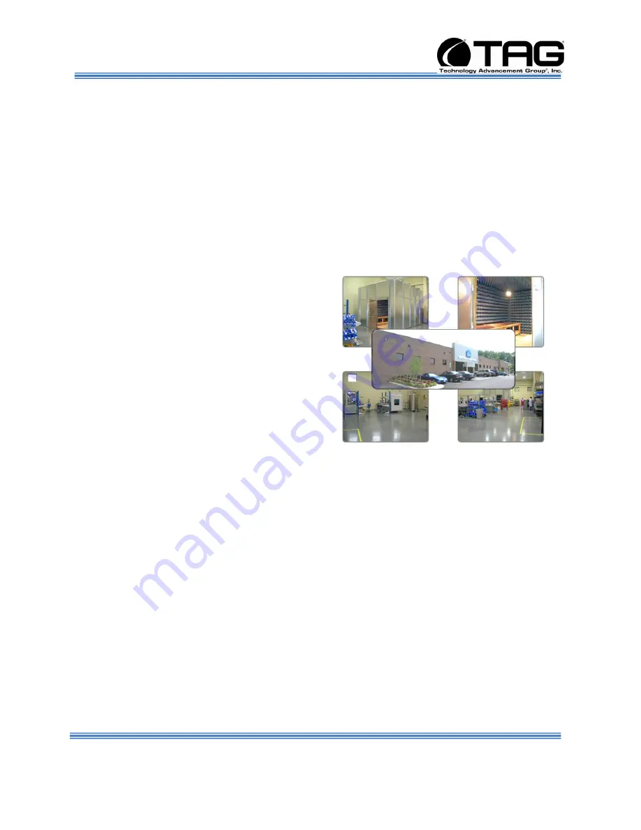
TAG prides itself on its engineering 
laboratories and facilities.  Over the past 
three years, TAG has invested in several 
pieces of equipment that allow TAG to test 
and certify products directly onsite to the 
harshest environmental requirements of 
military standards 

– including the MIL-STD-

810F and DO 160D.   

TAG’s onsite test equipment currently 
includes a Highly Accelerated Lifecycle 
Testing (HALT) Chamber, an 
Electromagnetic Interference (EMI) test chamber, and a high-/low-temperature thermal 
test chamber.  TAG’s facility also provides: 

  A floor plan designed to support a cellular manufacturing model with modular 

assembly lines 

  A dedicated 24-hour system burn-in room 

  A modern production status tracking and Enterprise Resource Planning (ERP) 

system with external web collaboration capabilities 

  Dedicated Quality Assurance workstations for system compliance and validation 

inspection 

2.2.2  Manufacturing and Integration 

TAG implements Cellular Manufacturing processes through our compartmentalized, 
state-of-the-art production facility to minimize waste byproducts and maximize 
production efficiency.  TAG’s manufacturing facility is physically partitioned to model the 
major philosophies of Lean Manufacturing

.  Consistent with the model, each of TAG’s 

production cells are capable of operating in isolation; however personnel and tools are 

Summary of Contents for SV-4103-X4

Page 1: ...4U Single Quad Core Xeon PICMG Server SV 4103 X4 Operations Manual TAG 22355 TAG Way Dulles VA 20166 ...

Page 2: ...t to ensure the correctness and completeness of the material in this document TAG shall not be liable for errors contained herein The information in this document is subject to change without notice TAG makes no warranty of any kind with regard to this material including but not limited to the implied warranties of merchantability and fitness for a particular purpose 1 1 Trademarks All trademarks ...

Page 3: ...ehensive Quality Assurance QA policy enforced through application of our UL registered ISO 9001 2000 certified processes enables TAG to rapidly deploy systems and solutions that reliably withstand the stresses of the tactical environment Today there are over 20 000 TAG systems deployed across various weapons platforms throughout the US Military TAG effectively balances all corporate assets our peo...

Page 4: ...ducts directly onsite to the harshest environmental requirements of military standards including the MIL STD 810F and DO 160D TAG s onsite test equipment currently includes a Highly Accelerated Lifecycle Testing HALT Chamber an Electromagnetic Interference EMI test chamber and a high low temperature thermal test chamber TAG s facility also provides A floor plan designed to support a cellular manuf...

Page 5: ... efficiency 2 2 3 Lifecycle Management TAG s world class Program Management discipline models the renowned methodologies of the Project Management Institute PMI to ensure successful completion of the task at hand Our Program Managers PMs serve as the voice of the customer driving requirements to which the rest of TAG s organization answers As an explicit tenet of TAG s corporate mission statement ...

Page 6: ... SV 4103 X4 Part Number 1007610 Page 6 of 80 Version 1 1 09 29 2009 Document Revision History Date Version Number Updated By Description of Changes 07 09 2008 1 0 Alan Huckerby Author 09 29 2009 1 1 Alan Huckerby Author ...

Page 7: ...l of our devices are based on the latest Intel and AMD technology Also this device doesn t use Intel Core Due or Pentium M technology only THS servers Configuration options include extended memory and enhanced video optimization All of our servers are backed by our world class lifecycle management and post sales support 3 1 1 Organization This manual is divided into the following chapters Chapter ...

Page 8: ... 4103 X4 17 6 1 1 SV 4103 X4 Specifications 17 6 1 2 SV 4103 X4 Components 20 6 1 3 Trenton 6680 Sys Host Board 20 6 1 4 Trenton 6680 Sys Host Board Components 22 6 1 5 PCI X Bus Frame Grabber 22 6 1 6 PCI X Bus Frame Grabber Board Components 24 6 1 7 MCG Series PICMG 1 3 PCI System Host Board 27 6 1 8 PCI Express System Host Board Components 28 6 1 9 PCI Analog Frame Grabber Board 29 6 1 10 PCI A...

Page 9: ...8 Identifying Server Components Using Device Manager 44 8 1 Working with Device Properties 47 8 2 Installing and Removing Hardware in Windows 49 8 2 1 Using the Add New Hardware Wizard 50 8 3 Installing Legacy Peripherals 51 8 3 1 Removing Legacy Peripherals 51 8 4 TAG Approved BIOS 54 8 4 1 BIOS Configuration for Nightvision 54 8 4 2 80 ...

Page 10: ...U Settings 56 Figure 8 14 IDE Configuration 56 Figure 8 15 IDE Configuration 57 Figure 8 16 Floppy Configuration Page 57 Figure 8 17 IDE Configuration Page 58 Figure 8 18 IDE Configuration Page 58 Figure 8 19 Floppy Configuration Page 59 Figure 8 20 Floppy Configuration Page 59 Figure 8 21 Super IO Configuration Page 60 Figure 8 22 Super IO Configuration Page 60 Figure 8 23 ACPI Configuration Page...

Page 11: ...n 72 Figure 8 45 Boot Settings Configuration Popup Screen 72 Figure 8 46 Boot Settings Screen 73 Figure 8 47 Boot Settings Configuration Screen 73 Figure 8 48 Boot Device Priority Screen 74 Figure 8 49 Boot Device Priority Screen 74 Figure 8 50 Boot Settings Screen 75 Figure 8 51 North Bridge Configuration Screen 75 Figure 8 52 Security Screen 76 Figure 8 53 South Bridge Chipset Configuration Scre...

Page 12: ...Chapter 1 SV 4103 X4 Part Number 1007610 Page 12 of 80 Version 1 1 09 29 2009 Chapter 1 Cautions and Warnings Electronically distributed Subject to user discretion when printed ...

Page 13: ...portant messages appear where mishandling of components is possible or when work orders can be misunderstood These messages also provide vital information associated with other aspects of system operation The word important is written as IMPORTANT both capitalized and bold and is followed by text in italics The italicized text is the important message 4 1 2 2 Warnings Warnings appear where overloo...

Page 14: ...the system Cautions are easy to recognize The word caution is written as CAUTION both capitalized and bold and is followed by text in italics The italicized text is the cautionary message 4 1 2 4 Notes Notes inform the reader of essential but non critical information These messages should be read carefully as any directions or instructions contained therein can help you avoid making mistakes Notes...

Page 15: ...Chapter 2 SV 4103 X4 Part Number 107610 Page 15 of 80 Version 1 1 09 29 2009 Chapter 2 SV 4103 X4 Electronically distributed Subject to user discretion when printed ...

Page 16: ...s with state of the art technology The newest Server can stand up to the harshest environments and is designed specifically to be fully customized to support unique mission critical applications Your system may contain components not described in this User Manual For detailed information on these components refer to the manufactures website or contact TAG Technical Support at tech support tag com ...

Page 17: ... of 80 Version 1 1 09 29 2009 6 SV 4103 X4 Figure 6 1 SV 4103 X4 6 1 1 SV 4103 X4 Specifications Chassis Power Supply Dimensions 7 H x 16 875 W x 15 D Weight 30 lbs Internal Power The internal ATX power supply is provided with two 28Vdc input power supplies ...

Page 18: ...ware Acoustically optimized Storage Internal 2 5 SATA Industrial Flash Drive PCI Graphics MSI 8600 GTS PCI E x16 NX8600GTS T2D256E_OC Graphics Card PCI Express Analog Video Frame Grabber Card PC2 COMP EXPRESS PCI E x1 Analog Video Capture Card PCI X Analog Frame Grabber Card X64AN QUAD PCI X Analog Frame Grabber Card PCI X Digital Frame Grabber Card X64 CL DUAL Digital Frame Grabber Card Operating...

Page 19: ...to 60 C Non operating Temperature Designed to meet 40 C to 70 C Humidity Designed to meet 0 90 non condensing Salt Fog Designed to meet MIL STD 810F Method 509 4 Fungus Mold Designed to meet MIL STD 810F Method 508 5 Shock The server is designed to meet MIL STD 810F Vibration The server is designed to meet MIL STD 810F Sand and Dust Protection The server is designed to meet MIL STD 810F EM I The s...

Page 20: ...hin your SV 4103 X4 For detailed information on the specific components installed refer the manufactures websites 6 1 3 Trenton 6680 Sys Host Board This Backplane Motherboard support s m ult iple PCI ExpressTM serial int erf aces t o opt ion card slot s and devices The f lexible Syst em Host board Provides PCI Express Graphics Card PCI Express Analog Video Frame Grabber Card PCI X Analog Frame Gra...

Page 21: ...Operations Manual SV 4103 X4 Part Number 107610 Page 21 of 80 Version 1 1 09 29 2009 Figure 6 2 Trenton 6680 Sys Host Board ...

Page 22: ...d voltages Software interface to monitor hardware values including HDD S M A R T On board Lithium battery and external battery input 0 60 C Compliance with EN55022 and EN61000 4 2 ESD UL609501 1 2003 First edition CSA C22 2 No 60950 1 03 First edition April 1 2003 RoHS and Lead free production Trenton s PICMG 1 3 compatible backplanes 170 mm x 170 mm 6 7 x 6 7 6 1 5 PCI X Bus Frame Grabber The X64...

Page 23: ...r independent cameras at the same time and offers independent control signals for each input channel to acquire transfer and track images accurately Supporting high resolution 8 bit image digitization the X64 AN Quad offers independent image paths creating virtually four frame grabbers in one slot Figure 6 4 PCI X Bus Frame Grabber ...

Page 24: ...Bus Frame Grabber Board Components Image time stamp for accurate object tracking of each input channel Concurrent acquisition from up to four independent format cameras High speed image transfers at up to 528MB s PCI X 66MHz compatible Supports Windows XP and 2000 Board Full length 64 bit PCI X 66MHz compatible Transfers Supports 5V and 3 3V slots ...

Page 25: ...75 ohms terminated Pixel jittter Video 0 714 VPP 75 ohms terminated Pixel jittter Partial scan mode Synchronization Supports composite video and separate horizontal and vertical sync input Horizontal Vertical Drive output LV TTL and TTL compatible Frame reset and WEN inputs for each channel Onboard memory 128MB Onboard frame buffer memory Pixel Formats Monochrome 8 bit pixel Transfers Real time tr...

Page 26: ...vide seamless interface to MS Windows applications Optional General purpose IO module supports Inputs and 8 TTL outputs Inputs support TTL and 24V operations TTL outputs support PNP and NPN operations Power Output Power on reset fused 12V DC output at 750 mA max for each input channel Software Microsoft Windows XP and Windows 2000 compliant Full support of DALSA s Sapera programming package Micros...

Page 27: ...ver class computing applications Dual Core processor options provide two and Quad Core processors provide four execution cores per CPU For dual processor board configurations each CPU has its own independent system bus to reduce data bottlenecks while maximizing processing throughput The four channel memory interface features DDR2 667 FB DIMMS with a maximum of 16GB NOTE This Unit provides a Singl...

Page 28: ...ssors that provide up to eight processor execution cores per board 1 2 8 An independent 1066 1333MHz system bus for each processor Support for 32 bit and 64 bit operating systems A four channel system memory interface with standard memory 16GB and extended memory 32GB support Six SATA 300 ports that support RAID 0 1 5 and 10 drive arrays Three Gigabit Ethernet interfaces and eight USB 2 0 ports Su...

Page 29: ... Manual SV 4103 X4 Part Number 107610 Page 29 of 80 Version 1 1 09 29 2009 6 1 9 PCI Analog Frame Grabber Board Figure 6 10 PCI Analog Frame Grabber Board Figure 6 11 PCI Analog Frame Grabber Board Block Diagram ...

Page 30: ...et faster 6 1 10 PCI Analog Frame Grabber Board Components Board Half slot PCI Express 1 0a compliant Acquisition 6 Composite Video or 2 Y C 4 CV and 1 YC OR 2 CV and 2 YC Standard RS170 NTSC CCIR and PAL formats Up to 8MB of frame buffer memory Image mirroring and vertical flip Adaptive 2 4 line comb filter for high accuracy chrominance and luminance separation Arbitrary horizontal and vertical d...

Page 31: ...s CPU 64MB system memory 10MB free hard drive space Dimensions PCI Express 6 677 16 95 cm Length x 4 20 10 7cm Height Power Max 1 8A at 3 3V Consumption 170mA at 12V Temperature Operating 0 C 32 F to 50 C 131 F Storage 40 C 40 F to 125 C 257 F Relative Humidity 5 to 95 non condensing Markings FCC Approved CE Approved 6 1 11 PCI X Digital Frame Grabber Compatible with one Base Medium or Full Camera...

Page 32: ...Operations Manual SV 4103 X4 Part Number 1007610 Page 32 of 80 Version 1 1 09 29 2009 Figure 6 12 PCI X Digital Frame Grabber Figure 6 13 PCI X Digital Frame Grabber Block Diagram ...

Page 33: ... Camera Link cameras Interfaces to digital area scan or linescan color or monochrome cameras Supports standard multi tap Camera Link configurations 1 Full camera 8 x 8 bit 1 Medium camera 4 x 8 bit 4 x 10 bit 4 x 12 bit 1 x 30 bit RGB and 1 x 36 bit 1 Base camera 3 x 8 bit 2 x 10 bit 2 x 12 bit 1 x 14 bit 1 x 16 bit and 1 x 24 bit RGB Alternate multi tap Camera Link configurations support 4 x 14 b...

Page 34: ...for external web synchronization supports cascaded divide and multiply Power Output Power on reset fused 12V 5V DC output at 1 5A Software Microsoft Windows NT 4 0 Windows 2000 and Windows XP compliant Full support of the Sapera programming package Compatible with Microsoft Visual Studio 6 0 and Net unmanaged code only Visual Basic 6 0 and Borland C Builder 5 5 or higher System Requirements PCI 64...

Page 35: ...clocked with its core running at 600 MHz and memory at 1600 MHz stock is 540 1400 MSI s NX8600GTS T2D256E OC videocard is based on the new nVIDIA GeForce 8600GTS core The card packs in a modest 256MB of GDDR3 memory This PCI Graphics card enhances image quality Brings the easiest way to optimize graphic quality Colorize your vision when browsing digital photographs Sharpens characters edges Figure...

Page 36: ...Memory NX8600GTS T2D256E OC videocard 700 MHz core 2100 MHz memory 256MB DDR3 Video Output Function Dual link DVI Support HDTV HDCP Support TV out Dual DVI Connectors GPU 675MHz Memory 2000MHz Performances Graphics Bus Technology PCI Express Memory 256MB Memory Interface 128 bit Memory Bandwidth GB sec 32 Fill Rate Billion pixels sec 10 8 RAMDACs MHz 400 Custom Cooling Solution ...

Page 37: ...t require high reliability storage in a low profile H 5mm x W 68 9 x L 100 25 package the industrial grade XceedLite is suited for use as rugged reliable boot drives in a wide range of communications applications including mobile and embedded computing medical automotive and industrial The XceedLite features enhanced reliability as a result of advanced on board error detection as well as correctio...

Page 38: ...Operating altitude up to 80 000 ft Operating shock 50G peak 2ms Operating vibration 15G peak to peak Power Input voltage 5 0V 5 Typical consumption Idle 60mA Sustained Read Write 110mA 130Ma Compliance CE UL EN 55022 Class B CISPR 22 Class B AS NZS 3548 Class B BSMI CNS 13438 Class B CAN CSA V 3 2001 04 VCCI FCC Part 15 Class B EN 61000 3 2 EN 61000 3 3 IEC 61000 4 2 3 4 5 6 8 11 Reliability MTBF ...

Page 39: ...timers These functions are configured in the CMOS Setup Section 8 4 BIOS Setup 6 2 1 Power Supply Two 300W DC power supply modules are supplied One 300W DC module will supply power solely to the backplane ATX connector The second 300W DC module will supply all other power requirements Including power supply to auxiliaries such as Fans HD etc Figure 6 17 Zippy Power Supply 6 2 2 Power Supply Compon...

Page 40: ... second Input to frame ground 1500 vac for 1 second Efficiency 65 typical at full load power good signal on delay 100ms to 500ms Overload Protection 130 20 Over Voltage Protection 5v 5 5v 7 0v 3 3v 4 0v 4 5v Short Circuit Protection 5v 12v 3 3v Emi Noise Filter fcc class a cispr22 class a Safety ul 60950 csa 22 2 iec60950 tuv en60950 Remote on off Control The unit shall accept a logic open collect...

Page 41: ...Series 24 V DC DC converters to meet conducted emission conducted susceptibility per MIL STD 461E and input transients per MIL STD 704E F The M FIAM5 accepts an input voltage of 14 36 Vdc and delivers output current up to 20 A 6 3 1 Vin Filter Features Transient protection MIL STD 704E F Environments MIL STD 810 MIL STD 202 Environmental stress screening Low profile mounting options Output current...

Page 42: ...Operations Manual SV 4103 X4 Part Number 1007610 Page 42 of 80 Version 1 1 09 29 2009 Chapter 3 Procedures Electronically distributed Subject to user discretion when printed ...

Page 43: ...at this time 4 At windows dialog box press Ctrl Alt Delete at once to login 5 Type in the correct user name and password and then press enter to login 6 Once the operator is logged on to the unit they could use the computer as they wish NOTE Assuming the SV 4103 X4is not connected to any network 7 2 SV 4103 X4 Shutdown 1 The operator needs to save all data and then close all applications 2 Once al...

Page 44: ... reset by shorting the CMOS restore to factory defaults jumper or by temporarily removing the CMOS battery 8 Identifying Server Components Using Device Manager The Device Manager is one of Windows most useful diagnostic tools It lets you see all of the devices attached to your computer and which resources they are each using To access the Device Manager do the following 1 Click Start point to Sett...

Page 45: ... Part Number 107610 Page 45 of 80 Version 1 1 09 29 2009 2 Double click the System icon Figure 8 2 Figure 8 2 System Properties 3 Click the Hardware tab and then click the Device Manager button Figure 8 3 Figure 8 3 Device Manger ...

Page 46: ...hidden devices indicates hidden devices are showing Click it again to clear the check mark Hidden devices include non PnP devices and devices that have been physically removed from the computer but have not had their drivers uninstalled The devices shown represent the computer s current hardware configuration information Any non functioning devices are displayed with an exclamation point indicatin...

Page 47: ... Number 107610 Page 47 of 80 Version 1 1 09 29 2009 8 1 Working with Device Properties To display a device s properties do the following 1 Access the Device Manager as described in steps 1 through 3 Figure 8 4 Figure 8 4 Device Manager ...

Page 48: ...ration information as well as the device manufacturer device type and location in the upper portion of the General tab The Device status box in the middle of the General tab displays the status of the device including any errors If the device has any problems the Device Status box briefly describes the problem and usually describes the appropriate course of action to correct the problem 3 Click Tr...

Page 49: ...installing peripheral drivers and making sure the new device didn t conflict with another device Theoretically if you have a computer designed for PnP and are using a PnP operating system like Windows installing a printer sound card modem or other peripheral is a simple matter of plugging in the device It s not always quite this simple Assuming you are using a PnP computer when you attach a PnP de...

Page 50: ...Hardware Wizard If the device is not working properly try using the Add New Hardware Wizard To run this wizard do the following 1 From the Start menu point to Settings and then click Control Panel Figure 8 6 Figure 8 6 Control Panel 2 Double click the Add Hardware icon Figure 8 7 Figure 8 7 Add Hardware Wizard ...

Page 51: ...ything that s no longer on the cutting edge 8 3 1 Removing Legacy Peripherals When removing a legacy peripheral from your system you need to let Windows know that the device is gone This enables Windows to reuse the resources places in memory and internal communications channels that it previously allocated to that device To tell Windows that you have removed a legacy device perform the following ...

Page 52: ...X4 Part Number 1007610 Page 52 of 80 Version 1 1 09 29 2009 2 Double click the System icon Figure 8 9 Figure 8 9 System Properties 3 Click the Hardware tab 4 Click the Device Manager button Figure 8 10 Figure 8 10 Device Manager ...

Page 53: ...ck the name of the item you have removed from your system If you don t see the item look for a category heading that describes the type of device you removed and then click the plus sign to its left to display a list of items in that category 6 From the Action menu click Uninstall 7 Click OK ...

Page 54: ...aded and tested with a specific BIOS version If you desire to have the BIOS updated consult TAG technical support in advance as updates to your approved BIOS may cause your system to become unstable or inoperable 8 4 1 BIOS Configuration for Nightvision Enter BIOS by pressing Delete when prompted in POST Once the BIOS Configuration Utility has been entered scroll to the exit tab using the arrow ke...

Page 55: ...n 1 1 09 29 2009 1 On the Main BIOS System Overview screen ensure System Time and Date are correct Press Enter Figure 8 11 Figure 8 11 System Overview 2 On the Advanced Settings screen select CPU Configuration Press Enter Figure 8 12 Figure 8 12 CPU Configuration Screen ...

Page 56: ... 29 2009 3 On the CPU Configuration screen No Change Press Enter Figure 8 13 Then press Escape to return to Advanced Settings screen Figure 8 13 Advanced CPU Settings 4 On Advanced BIOS screen Scroll down to IDE Configuration Press Enter Figure 8 14 Figure 8 14 IDE Configuration ...

Page 57: ...09 5 No Change required for IDE Configuration Press Enter Then press Escape to return to Advanced Settings screen Figure 8 15 Figure 8 15 IDE Configuration 6 On Advanced Settings screen Scroll down to Floppy Configuration Press Enter Figure 8 16 Figure 8 16 Floppy Configuration Page ...

Page 58: ...2009 7 On Advanced Settings screen Scroll down to IDE Configuration Press Enter Figure 817 Figure 8 17 IDE Configuration Page 8 No Change required for IDE Configuration Press Enter Then press Escape to return to Advanced Settings screen Figure 8 18 Figure 8 18 IDE Configuration Page ...

Page 59: ...ed Settings screen Scroll down to Floppy Configuration Press Enter Figure 8 19 Figure 8 19 Floppy Configuration Page 10 On the Floppy Configuration page change Floppy A to Disabled Press Enter Then press Escape to return to Advanced Settings screen Figure 8 20 Figure 8 20 Floppy Configuration Page ...

Page 60: ...dvanced Settings screen Scroll down to SuperIO Configuration Press Enter Figure 8 21 Figure 8 21 Super IO Configuration Page 12 On the Super IO Configuration Page no changes are necessary Figure 8 22 Then press Escape to return to Advanced Settings screen Figure 8 22 Super IO Configuration Page ...

Page 61: ...Advanced Settings screen Scroll down to ACPI Configuration Press Enter Figure 8 23 Figure 8 23 ACPI Configuration Page 14 On the ACPI Configuration Page change Power Supply Shutoff to Auto Figure 8 24 Then press Escape to return to Advanced Settings screen Figure 8 24 ACPI Configuration Page ...

Page 62: ...nd press Enter On the South Bridge ACPI Configuration Page no changes are necessary Figure 8 25 Then press Escape to return to Advanced Settings screen Figure 8 25 South Bridge ACPI Configuration Page 16 On Advanced Settings screen Scroll down to ACHI Configuration Press Enter Figure 8 26 Figure 8 26 ACHI Configuration Page ...

Page 63: ...2009 17 No Change on the ACHI Configuration page Figure 8 27 Then press Escape to return to Advanced Settings screen Figure 8 27 ACHI Configuration Page 18 On Advanced Settings screen scroll down to SMBIOS Configuration Press Enter Figure 8 28 Figure 8 28 SMBIOS Configuration Page ...

Page 64: ...MBIOS Configuration Page no changes are necessary Figure 8 29 Then press Escape to return to Advanced Settings Screen Figure 8 29 SMBIOS Configuration Page 20 On Advanced Settings screen scroll down to Remote Access Configuration Press Enter Figure 8 30 Figure 8 30 Remote Access Configuration Page ...

Page 65: ... 29 2009 21 On the Remote Access Configuration Page no changes are necessary Figure 8 31 Then press Escape to return to Advanced Settings screen Figure 8 31 Remote Access Configuration Page 22 On Advanced Settings screen scroll down to Trusted Computing Press Enter Figure 8 32 ...

Page 66: ...9 29 2009 Figure 8 32 Trusted Computing Page 23 No Change on the Trusted Computing page Figure 8 33 Then press Escape to return to Advanced Settings screen Figure 8 33 Trusted Computing Page 24 On Advanced Settings screen Scroll down to MPS Configuration Press Enter Figure 8 34 ...

Page 67: ...gure 8 34 MPS Configuration Page 25 No Change on the MPS Configuration page Figure 8 35 Then press Escape to return to Advanced Settings screen Figure 8 35 MPS Configuration Page 26 No Change on the MPS Configuration page Figure 8 36 Then press Escape to return to Advanced Settings screen ...

Page 68: ...9 29 2009 Figure 8 36 MPS Configuration Page 27 On Advanced Settings screen scroll down to USB Configuration Press Enter Figure 8 37 Figure 8 37 USB Configuration Page 28 No Change on the USB Configuration page Figure 8 38 Then press Escape to return to Advanced Settings screen ...

Page 69: ...9 of 80 Version 1 1 09 29 2009 Figure 8 38 USB Configuration Page 29 On Advanced Settings screen scroll across to PCI PnP and Press Enter Figure 8 39 Figure 8 39 PCI PnP Screen 30 On the PCI PnP Page scroll down to Plug Play O S and press Enter On the Pop ...

Page 70: ... 70 of 80 Version 1 1 09 29 2009 up screen select YES and press Enter Figure 8 40 Figure 8 40 Plug Play Configuration Popup Screen 31 On PCI PnP screen Scroll down to Onboard VGA Controller Press Enter Figure 8 41 Figure 8 41 Onboard VGA Controller Screen ...

Page 71: ...29 2009 32 On the Onboard VGA Controller screen Select Onboard VGA Controller Then Press Enter Figure 8 42 Figure 8 42 Onboard VGA Controller Screen 33 On Onboard VGA Controller Popup screen Select Disabled Press Enter Figure 8 43 Figure 8 43 Onboard VGA Controller Popup Screen ...

Page 72: ...ss to the BOOT tag and press Enter Then select Quiet Boot and press Enter Figure 8 44 Figure 8 44 Boot Setting Configuration Screen 35 On the Boot Settings Configuration Popup screen select Disabled Press Enter Figure 8 45 Then press Escape to return to Boot Setup screen Figure 8 45 Boot Settings Configuration Popup Screen ...

Page 73: ... Settings screen select Boot Settings Configuration Press Enter Figure 8 46 Figure 8 46 Boot Settings Screen 37 On the Boot Settings Configuration screen select Quick Boot No changes are necessary Press Enter to return to the Main Boot screen Figure 8 47 Figure 8 47 Boot Settings Configuration Screen ...

Page 74: ...ll down and select Boot Device Priority Press Enter Figures 8 48 Figure 8 48 Boot Device Priority Screen 39 On Boot Device Priority screen the boot order should be HDD PM SMART XCEED Network IBA GE Slo and Network IBA GE Slo Figure 8 49 Press Escape to return to Boot Settings screen Figure 8 49 Boot Device Priority Screen ...

Page 75: ... 40 On Boot Settings screen scroll down to Hard Drive Priority Press Enter Figure 8 50 Figure 8 50 Boot Settings Screen 41 On the Hard Disk Drives Page no changes are necessary Press Escape to return to the Boot Settings screen Figure 8 51 Figure 8 51 North Bridge Configuration Screen ...

Page 76: ...cross to Security No changes are necessary Figure 8 52 Figure 8 52 Security Screen 43 Scroll across to the Chipset tab and press Enter Select South Bridge Chipset Configuration Press Enter Figure 8 53 Figure 8 53 South Bridge Chipset Configuration Screen 44 On the South Bridge Configuration screen select Onboard LAN Boot ROM ...

Page 77: ...nter On the popup screen select Enabled and press Enter Then press Escape to return to the Chipset screen Figure 8 54 Figure 8 54 Onboard LAN Boot ROM Screen 45 On Chipset screen scroll down to ESB2 PCI X Hub Configuration Press Enter Figure 8 55 Figure 8 55 ESB2 PCI X Hub Configuration Screen ...

Page 78: ...o changes are necessary Figure 8 56 Press Escape to return to Chipset screen Figure 8 56 ESB2 PCI X Hub Settings Screen 47 Scroll over to the Exit tab and press Enter Select Save Changes and Exit Then press Enter Figure 8 57 Figure 8 57 Save Changes and Exit Screen 48 Select OK on the Popup screen and Press Enter Figure 8 58 ...

Page 79: ...Operations Manual SV 4103 X4 Part Number 107610 Page 79 of 80 Version 1 1 09 29 2009 Figure 8 58 Save Configuration Screen ...

Page 80: ...nical Support USA 1 800 824 7693 Outside USA While every precaution has been taken to ensure the accuracy and completeness of this literature TAG assumes no responsibility and disclaims and liability for damage resulting from use of this information or for any errors or omissions ...

Reviews: