XT-1/XT Mini Manual
13-111 05, 2015-08-14
Page 15 of 32
changed under Settings…/Interfaces…/Ethernet in the web interface. A reboot is required to activate new
settings.
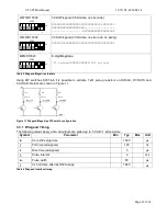
For convenience, it is possible to force the reader to use a fixed IP address by setting DIP switch S101:3 to
ON before starting the reader. The IP address will then be 169.254.1.1 and the subnet mask 255.255.0.0. A
PC that is directly connected to a reader will usually get an IP address in this subnet automatically.
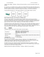
The built-in Ethernet switch (XT-1 only) makes it possible to connect multiple readers in a chain.
Figure 14 Readers connected in a chain using the built-in Ethernet switch
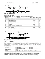
The reader supports ICMP echo request/reply (ping) to simplify network troubleshooting. By default,
ping beep is enabled which means that the reader beeps when it receives a ping packet. Ping beep can be
used to identify which reader that has a specific IP address or to determine if ping packets get lost on the
way to the reader or from the reader. Ping beep can be disabled using the web interface.
The reader can work as a TCP server and/or TCP client. As a client, the reader automatically connects to a
specified TCP server when it has data to send. The IP address and port of the server and the protocol to
use can be configured under Settings…/Interfaces…/Ethernet in the web interface. Supported protocols are
Push and TAGP. As a TCP server, the reader supports several protocols, including TAGP.
RS232
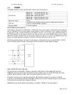
The RS232 interface can be used for communication with a host system.
Connections
RS232:TXD Transmitted data to host
RS232:RXD Received data from host
RX232:GND Signal ground #2
Max cable length
10 m
Wire size
Specification according to EIA RS232C. Belden 9184 or Belden 9502 are
recommended.
Max Baud rate
115.2 kb/s (default)
Table 9 RS232 connection overview
The default output of the RS232 interface is tag data in ASCII format. If SecureMarkID
®
tags from
TagMaster are being used (recommended) the numeric identity is sent out. If other EPC tags are being
used the default output is the EPC data. The data is followed by CR+LF ("\r\n").
A TAGP connection can be initiated by sending the HELOTAGP message to the reader. The TAGP
connection is terminated with the QUIT message. Other protocols can be enabled using the web interface.
These protocols are described in separate manuals.
All RS232 settings are available under Settings…/Interfaces…/RS232 in the web interface.
Summary of Contents for XT Mini
Page 1: ...XT 1 XT Mini Manual ...


