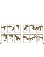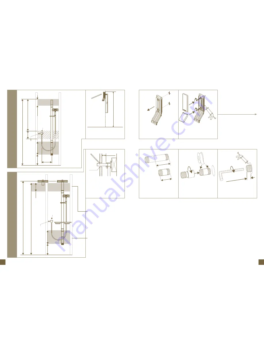
measure x and subtract 13mm.
This is the length of the brass
nipple required to install the outlet
connector
Set bracket aside, drill clearance
into lining then pre-drill support
ensure edge is plumb, mark plumb
line to floor and mark screw holes
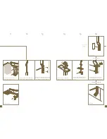
Wrap both ends of brass nipple
with Teflon tape and screw on
drencher outlet adaptor. Screw
assembly into wingback
Seal holes. drive in screws (and
wall plugs where appropriate). Clip
on covers
Tighten using using a 10mm hex
key, check dimension and seal the
wall
2
1
3
4
go to 12 on page 6
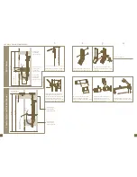
Rail Shower
Shower Sy
st
em and Dr
ench Shower
Fastening Zone
– load-bearing
support required
Fastening Zone
– load-bearing
support required
380mm
360mm
Hole
Ø25mm
2100mm
Recommended
outlet height
20
70mm
240mm
Floor
Elbow height at install
er
’s discr
etion
(R
ecommended
) 2010mm
X
X - 13mm
16mm +/- 3mm
pre Wall lining requiremenTS
install properly anchored female
1/2 wingback at least 25mm from
the front of the unlined wall. Screw
in test nipple. When the wall is
finished mark the test nipple at the
wall surface and remove the nipple
Ø25mm
25mm (Min.)
Standard Rail
Fastening Zone
-load bearing
support required
Short Rail (13-8302)
Fastening Zone
-load bearing
support required
Fastening Zone
-load bearing
support required
2020mm
930mm
180mm
180mm
Floor
300mm
Min.
Hole
Ø25mm
380mm
360mm
Elbow height at install
er
’s discr
etion


