90
3.5.2 Installation
3.5.2.1 Installation of HCS-4360/61/62/63 series
congress unit
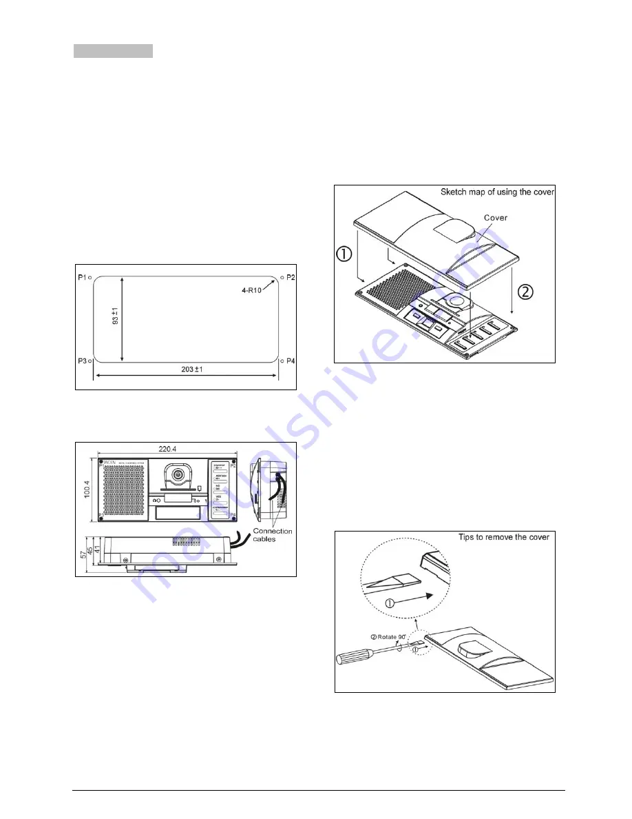
a. Cut a hole in the table according to the dimensions
in figure 3.26;
b. Put the congress unit into the hole and drill four Ø
2 mm holes with 10 mm depth at the positions P1
to P4 of the fixing screws;
c. Run the two cables - mounted laterally on the
congress unit - according to the mounting
feasibilities existing on site.
d. Put the discussion unit into the hole and fix it with
screws at P1, P2, P3 and P4.
Figure 3.26
Fixing hole positioning diagram
of
HCS-4360/61/62/63 series congress unit (unit: mm)
Figure 3.27 Flush-mounted installation diagram of the
HCS-4360/61/62/63 series congress unit
3.5.2.2 Installation of the protective cover of
HCS-4360/61/62/63 series congress unit
If not in use for a long time, just pull out the microphone
and put on the protective cover:
a. Hook up the protective cover on the left side;
b. Then press the protective cover tightly on the right
side.
Figure 3.28 Installation diagram of the protective cover
of HCS-4360/61/62/63 series congress unit
3.5.2.3 Dismounting the protective cover of the
HCS-4360/61/62/63 series congress unit
a. Prepare a straight screwdriver;
b. Insert the straight screwdriver into the gap at the
right lower side of the protective cover and rotate
the screwdriver by 90 degrees, the protective
cover will be separated from the congress unit.
Figure 3.29 Dismounting the protective cover of
HCS-4360/61/62/63 series congress unit
Summary of Contents for HCS-4100/50 Series
Page 46: ...33 Figure 2 10 Floor mode setting Normal Mode Figure 2 11 Floor mode setting Insert Mode...
Page 47: ...34 Figure 2 12 Floor mode setting Sync Line Out1 Mixer...
Page 59: ...46 Figure 3 4 Cutout of HCS 48U8 series flush mounted congress unit unit mm...
Page 61: ...48 Figure 3 6 Cutout of HCS 48U9DFFF flush mounted congress unit unit mm...
Page 62: ...49 3 2 2 2 Installation Figure 3 7 Installation of HCS 48U7 series flush mounted congress unit...
Page 63: ...50 Figure 3 8 Installation of HCS 48U8 series and HCS 48U9 series flush mounted congress unit...
Page 65: ...52 Figure 3 11 Disassembly caution of HCS 48U8 and HCS 48U9 series flush mounted congress unit...
Page 130: ...117 Figure 3 43 Installation of HCS 4325U 50 congress unit unit mm...
Page 143: ...130 Figure 3 57 Multi function connector connected to the HCS 4341 50 series congress unit...
Page 155: ...141 Figure 3 72 Multi function connector connected to HCS 4841 42 43 series congress units...
Page 170: ...156 4 1 Functions and indications Front Side Bottom Figure 4 1 HCS 4385U 50 Interpreter unit...
Page 223: ...www taiden com TAIDEN INDUSTRIAL CO LTD Copyright by TAIDEN Last Revision 06 2013...


