5-13
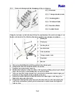
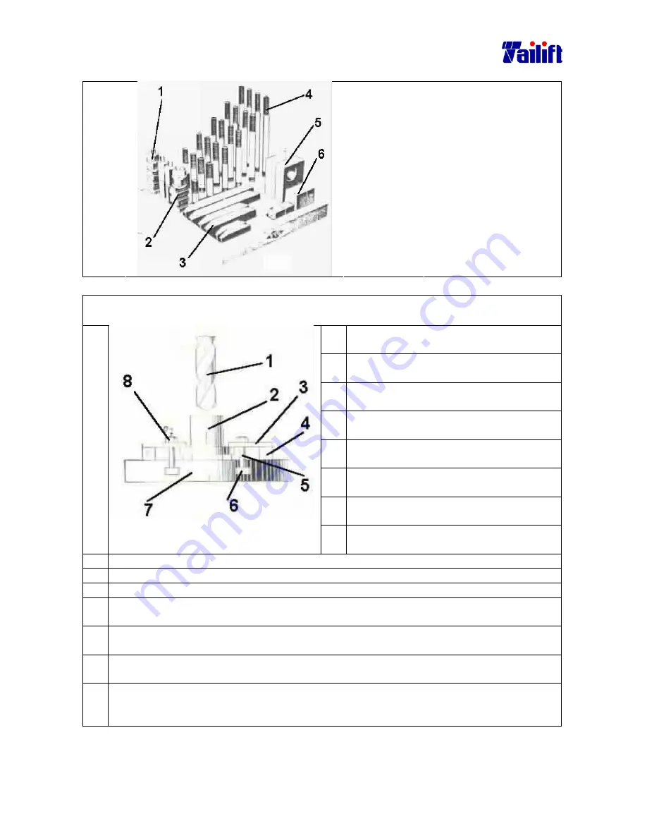
5.3.3 Universal clamp and the clamping of the work piece.
(
(
(
(
1
)
)
)
)
Hex nuts
(
(
(
(
2
)
)
)
)
T shape chamfer nuts
(
(
(
(
3
)
)
)
)
Stacking plate
(
(
(
(
4
)
)
)
)
Twin head bolts
(
(
(
(
5
)
)
)
)
Insertion block
(
(
(
(
6
)
)
)
)
Ladder block
Clamp the work piece as the following
:(
:(
:(
:(
Since the combination of the universal clamp is very
flexible and abundant, The following diagram is applied as an exemplary description.
1.
Drilling bit
2.
Work piece
3.
Stacking block
4.
Insertion block
5.
Twin head bolts
6.
T shape chamfer bolts
7.
Worktable
8.
Hex but
a.
Move away the drilling bit or lift the gearbox to the utmost point.
b.
Using brush, clean the worktable and the vise surface.
c.
Clean the vise surface using clean rag.
d.
Position the work piece on the vise surface. If it is piercing drilling, please insert a block
under the work piece so that drilling into vise can be avoided.
e.
After screwing the T shape chamfer nut to the twin head bolts with suitable length, put
it into the T shape chamfer of the worktable or the base.
f.
Choose the insertion block or ladder block that is the same high as work flange. Put
them in the other side of the bolts.
g.
Using holed stacking block, place them onto the bolts, with one of its side pressing the
work flange and another pressing the insertion block or ladder block, then tighten it
with hex nuts.
Summary of Contents for TPR1100
Page 7: ...1 6 Arm elevating motor For TPR 720A TPR 820A TPR 920A Arm elevating motor For TPR 1100...
Page 30: ...5 4 5 1 2 For TPR 1100 The front view of TPR 1100...
Page 40: ...5 14 Examples of clamping using the universal clamp...
Page 81: ...9 6 9 6 Electrical Circuit Diagram For TPR720A TPR820A TPR920A Standard...
Page 84: ...9 9 9 8 Electrical Circuit Diagram For TPR1100 Standard...

