0-2
Section
Content
page
4.2
Transportation..……………………………………………………….…
4-2
4.2.1 The diagram of the machine weight and its gravity center...……………
4-2
4.2.2 The movement of the machine……. ……………………………………
4-2
4.2.3 The order to pack..………………………………………………………
4-3
4.3
Installation of the machine..……………………………………………..
4-4
4.3.1 Have the machine set onto the fastening bolts of the crate base...………
4-4
4.3.2 Level adjusting…………………………………………………………..
4-5
4.3.3 The installation of the electricity...……………………………………...
4-5
4.4
The test after installation………………………………………………...
4-6
4.5
The procedure for dismantling the machine…..………………………...
4-6
CHAPTER 5 Operation
……………………………………………………………..
5-1
5.1
A brief introduction to the relevant operation hardware………………...
5-1
5.1.1 ( For TPR-720A, TPR-820A, TPR-920A)………………………………
5-1
5.1.2 ( For TPR-1100)…………………………………………………………
5-4
5.1.3 Safty protective device…………………………………………………..
5-7
5.2
Instruction to switches..…………………………………………………
5-8
I ( For TPR-720A, TPR-820A, TPR-920A)………………………………
5-8
II ( For TPR-1100)….……………………………………………………...
5-11
5.3
Installation of the clamp
(
work piece….……………………………….
5-12
5.3.1 General...………………………………………………………………...
5-12
5.3.2 Introduction of the vise and the clamping of the work piece...………….
5-12
5.3.3 Universal clamp and the clamping of the work piece…………………...
5-13
5.4
Installation and change of the drilling bit……………………………….
5-15
5.4.1 The assembly and disassembly of the drilling head and clamp...……….
5-16
5.4.2 The assembly and disassembly of the straight handle drill bit….………
5-18
5.5
Power on and off..……………………………………………………….
5-19
5.5.1 Power on..……………………………………………………………….
5-19
5.5.2 Power off..……………………………………………………………….
5-19
5.6
Work light..……………………………………………………………...
5-19
5.7
Cutting fluids...………………………………………………………….
5-19
5.8
Elevating the arm..………………………………………………………
5-20
5.9
Rotate the arm right or leftwards.……………………………………….
5-21
5.10
Rotate the arm to or backwards...……………………………………….
5-22
5.11
Change the spindle speed.……………………………………………….
5-23
5.11.1 For TPR-720A, TPR-820A, TPR-920A...……………………………….
5-23
I Speedometer...…………………………………………………………...
5-23
II Change spindle speed...………………………………………………….
5-24
5.11.2 For TPR-1100….………………………………………………………...
5-25
I The speedometer at the time when the pole switch is in high position….
5-25
II Change spindle speed…………………………………………………...
5-26
III
The speedometer at the time when the pole switch is in low position…..
5-27
Summary of Contents for TPR1100
Page 7: ...1 6 Arm elevating motor For TPR 720A TPR 820A TPR 920A Arm elevating motor For TPR 1100...
Page 30: ...5 4 5 1 2 For TPR 1100 The front view of TPR 1100...
Page 40: ...5 14 Examples of clamping using the universal clamp...
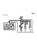
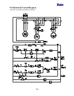
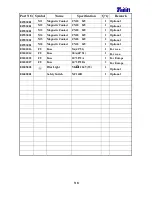
Page 81: ...9 6 9 6 Electrical Circuit Diagram For TPR720A TPR820A TPR920A Standard...
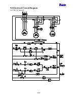
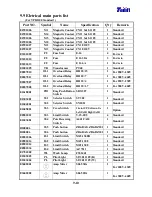
Page 84: ...9 9 9 8 Electrical Circuit Diagram For TPR1100 Standard...


