5-13
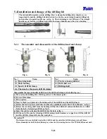
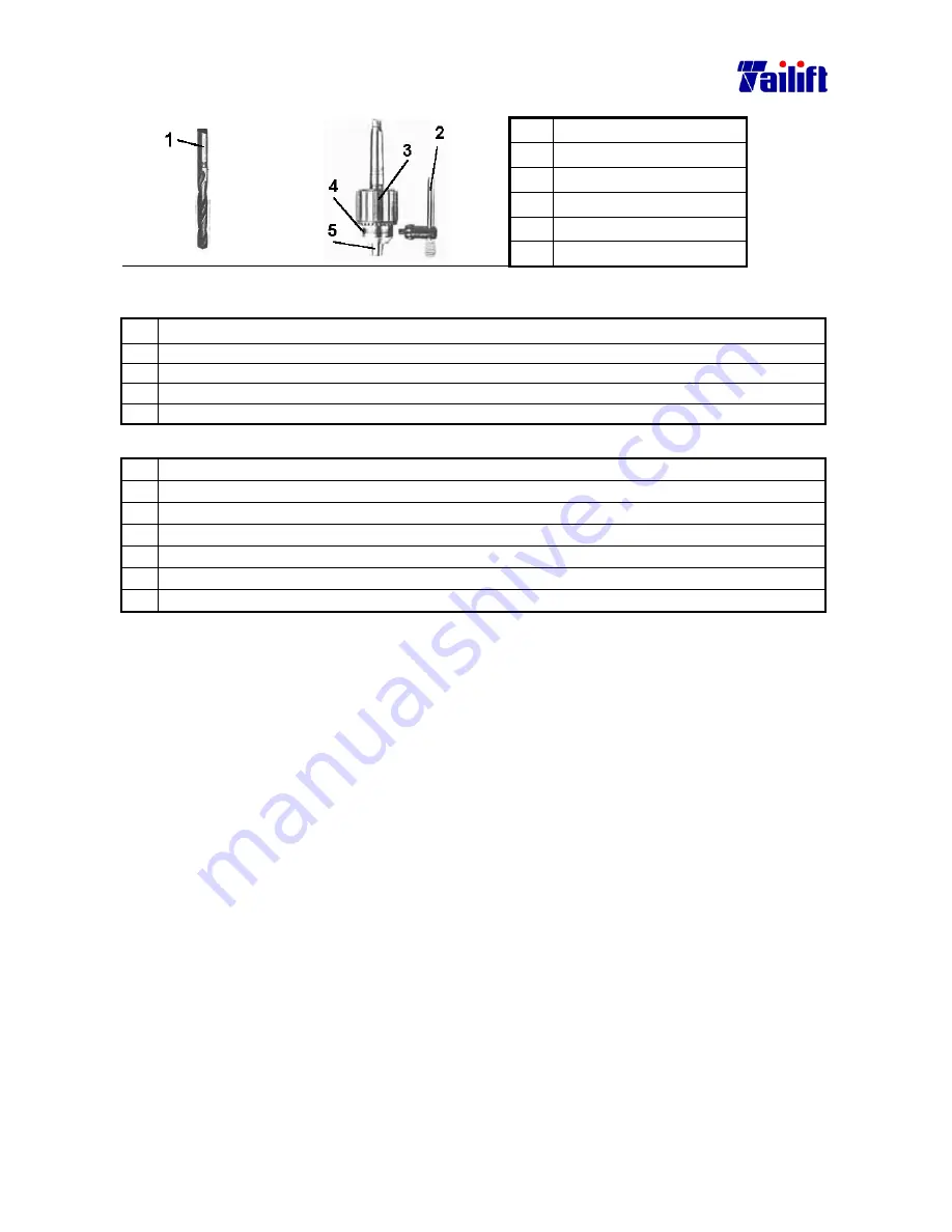
5.4.2 The assembly and disassembly of the straight handle drill bit
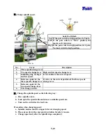
No.
Term
(1) Drill bit
(2) Drill spanner
(3) Tightening ring
(4) Hole for drill spanner.
(5) Drill bit clamp head.
Fig. a.
Fig. b.
Disassemble the straight drill bit as the following way:
a. Move away the drilling bit or lift the gearbox to the utmost point.
b. Power
off.
c. Put on gloves.
d. Put the drill spanner into the hole for tightening.
e. Rotate the spanner counter clockwise till the clamp head falls.
Assemble the straight handle drill bit as the following way:
a. Move away the drilling bit or lift the gearbox to the utmost point.
b. Power
off.
c. Put on gloves.
d. Adjust the tightening ring till the drill bit can be inserted.
e. Insert the drill bit into the clamp head at least 25 mm.
f. Put the drill spanner into the hole for tightening.
g. Rotate the spanner clockwise till the drill bit is tightened.
Precaution
:
The drill bit must be inserted at least over 25 mm, otherwise the bit get
easily broken or
can’t drill very precisely.
5.5 Power on and off.
5.5.1 Power on
a.
Turn outside main switch to ”ON” position.
b.
Turn the machine power switch to ”ON” position.
5.5.2 Power off
a.
Turn the machine power switch to ”OFF” position.
b.
Turn outside main switch to ”OFF” position.
Precaution
:
When at emergency, please press down the emergent stop button to shut down the
power supply.
But the emergent stop button can’t be used as a switch for normally stopping
machine or normal power off.
Summary of Contents for TPR1230
Page 11: ...1 6 z Gearbox For TPR 1230 TPR 1230H For TPR 1600H TPR 2000H z Hydraulic oil pump...
Page 74: ...9 4 9 4 Electrical circuit diagram For TPR 2000H CE Standard...
Page 83: ...9 13 9 9 Electrical circuit diagram For TPR 1230 Standard...
Page 84: ...9 14 9 10 Electrical circuit diagram For TPR 1230H Standard...
Page 85: ...9 15 9 11 Electrical circuit diagram For TPR 1600H TPR 2000H Standard...


