6-2
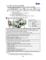
6.2.2(For TPR-1600H/ TPR-2000H)
Fig.
a.
Fig.
b.
Fig.
c.
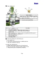
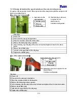
The relevant names
The relevant names
No. name
No.
name
1. Release
switch
3.
Adjusting nut
2. Clamping
switch
4.
Fastening nut
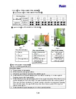
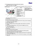
Adjust the arm clamping lever as follows:
a. Press the figure1 shown in the bottom. Referring to the up right picture, release the
button after pointing the arrow head to b. The clamping device is released now.
b. Release the fastening nuts, totally 5 pieces, in the figure c and mark 4.
c. Using a wrench, adjust the nuts counter clockwise about 180°. (totally 5 pieces bolts)
d. Fasten the nuts, marked 4 in the figure c. (totally 5 pieces bolts)
e. Press the figure2 shown in the bottom left picture 1. Referring to the up right picture,
release the button after pointing the arrowhead to A. The clamping device is tightened
now.
Summary of Contents for TPR1230
Page 11: ...1 6 z Gearbox For TPR 1230 TPR 1230H For TPR 1600H TPR 2000H z Hydraulic oil pump...
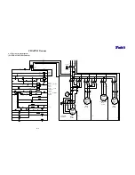
Page 74: ...9 4 9 4 Electrical circuit diagram For TPR 2000H CE Standard...
Page 83: ...9 13 9 9 Electrical circuit diagram For TPR 1230 Standard...
Page 84: ...9 14 9 10 Electrical circuit diagram For TPR 1230H Standard...
Page 85: ...9 15 9 11 Electrical circuit diagram For TPR 1600H TPR 2000H Standard...

