9-3
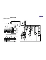
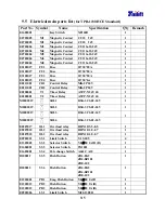
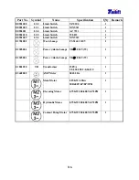
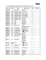
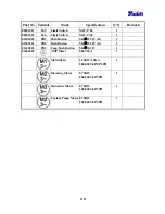
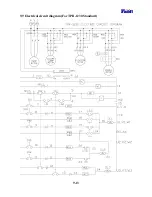
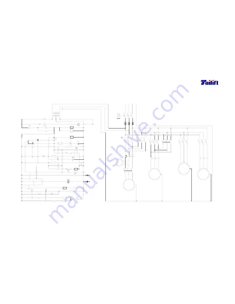
9.3 Electrical circuit diagram
(For TPR-1600H CE Standard)
MS1-1
LS4
PB3
23
SS2
30
SS3
25
6
PB3
6
22
To MS5
CR2-1
26
27
31
32
SS3
33
MS2-1
28
LS5
17
T3
T3
T3
18
9
SOL4
CR2
MS1
MS2
MS6
34
OL1
29
CR2-2
SOL5
12
MS4-1
9
LS2
11
SOL3
MS3
OL2
CR1-2
5
8
15
PB1
4
1
3
110V
24V
0V
FU4
MS5
T4-1
LS3
14
15
17
9
T1
T2-2
T2
16
10
T1
8
6
CR1-1
PB2
1
SS1
1
15
12
MS3-1
SOL1
LS1
SOL2
11
7
T1
OL2
MS4
35
T2
2
CR1
PB2
T4
PL
380V
500VA
TR
220V
E
3.5mm
2
V3
W3
U3
3~
M1
5.625Kw
Motor
Main
Coolant Pump Motor
Forward
U3, V3, W3
Reverse
U, V, W
U2, V2, W2
Down
~
M1
A
U2
3~
Motor
Elevator
1.5Kw
M2
2
5.5mm
2mm
2
V2
W2
L2
5.5mm
FU3
Up
Hydraulic Motor
U1, V1, W1
Work Lamp
2
35
MS1
L11
FU1
L12
FU2
Key Switch
5.5mm 5.5mm
2
2
L1
OL1
MS2
MS3
L13
OL2
MS4
5.5mm
2
2
L3
PE
0.1Kw
2mm
2
3~
Coolant Pump
M4
Motor
Hydraulic
0.5mm
Motor
0.75Kw
2
M3
3~
V
U
W
MS6
U1
MS5
V1
W1
OL3
4
Summary of Contents for TPR1230
Page 11: ...1 6 z Gearbox For TPR 1230 TPR 1230H For TPR 1600H TPR 2000H z Hydraulic oil pump...
Page 74: ...9 4 9 4 Electrical circuit diagram For TPR 2000H CE Standard...
Page 83: ...9 13 9 9 Electrical circuit diagram For TPR 1230 Standard...
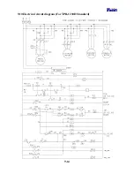
Page 84: ...9 14 9 10 Electrical circuit diagram For TPR 1230H Standard...
Page 85: ...9 15 9 11 Electrical circuit diagram For TPR 1600H TPR 2000H Standard...


