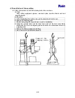
4-5
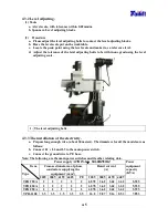
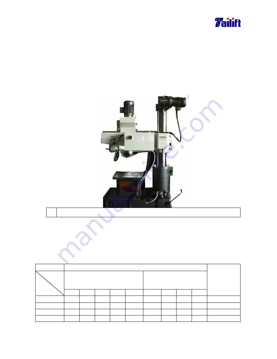
4.3.2 Level adjusting.
(1) Tools
a. A level scale, with tolerance within 0.02mm/m
b. Spanners, Level adjusting blocks.
(2) Procedure
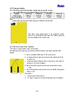
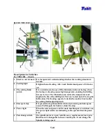
a. Please adjust the level adjusting bolts to contact the level adjusting blocks.
b. Have the level scale put on the worktable.
c. Locate the peak point using the level scale and make it as a reference level.
d. Adjust the tolerance of the level adjusting bolts to be within one grad using the level
adjusting scale.
1. The level adjusting bolts.
4.3.3 The installation of the electricity.
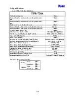
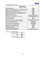
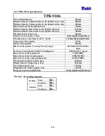
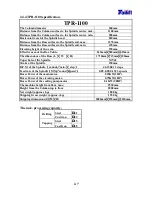
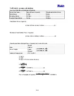
a. Prepare long enough wire. (about 30 meters). The diameters for all the models are as
follows:
b. Connect L1
、
、
、
、
L2 and L3 to the main power switch.
c. Connect the ground wire to PE base.
Note: The following are the main power switches and its other relating data.
Power supply AC
±
±±
±
10%1
Φ
Φ
Φ
Φ
50/60HZ
±
±±
±
1HZ
Cross-sectional area of phase
conductors supplying the
equipment` (mm
2
)
Rated current
(A)
Item
Type
220V 380V 415V 440V
PE
220V 380V 415V 440V
Power
equipment
capacity
(KVA)
TPR-720A
2
2
2
2
2
6.578
3.62
3.62
3.62
5.935
TPR-820A
2
2
2
2
2
6.578
3.62
3.62
3.62
5.935
TPR-920A
2
2
2
2
2
6.578
3.62
3.62
3.62
5.935
TPR-1100
3.5
3.5
3.5
3.5
3.5
16.2
9.87
9.14
8.53
7.853
Summary of Contents for TPR720A
Page 7: ...1 6 Arm elevating motor For TPR 720A TPR 820A TPR 920A Arm elevating motor For TPR 1100...
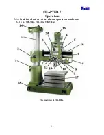
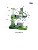
Page 30: ...5 4 5 1 2 For TPR 1100 The front view of TPR 1100...
Page 40: ...5 14 Examples of clamping using the universal clamp...
Page 81: ...9 6 9 6 Electrical Circuit Diagram For TPR720A TPR820A TPR920A Standard...
Page 84: ...9 9 9 8 Electrical Circuit Diagram For TPR1100 Standard...

