


CNC-110A Series C-03/C-13 User's manual
11
έᚊཝҋજ̼ѣࢨ̳Φ
TAILY AUTOMATION CO.,LTD.
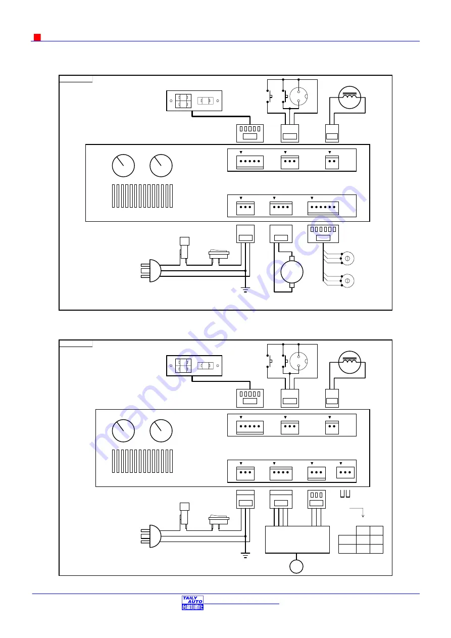
10.2.External wiring diagram for CNC-110AS
CN5
CN1
CN6
CN3
1
2
110AS-001E.sch
CN2
CN4
H.S.
L.S.
RES/
REV
RUN/
STOP
COM
M
BRAKER (DC24V 12W]
2
3
POWER SW
FUSE
10A 250V
EARTH
AC POWER
WINDING SPINDLE SHAFT
0.5HP DC MOTOR
1
2
3
4
5
6
H.S.
L.S.
1
2
3
1
2
3
EXTERNAL SPEED ADJUST
INTERNAL SPEED ADJUST
(OPTION)
FOOT SW
TURNS COUNTER
CNTB-03B/CNTB-03C
10.3.External wiring diagram for CNC-110AE
CN5
CN1
CN6
CN3
1
2
110AS-002E.sch
CN2
CN4
H.S.
L.S.
RES/REV
RUN/STOP
COM
M
BRAKER [DC24V 12W]
2
3
POWER SW
FUSE
10A 250V
EARTH
AC POWER
JP1
CO
M
CW/RUN
CCW/DIR
SLOW
V+
V-
SPEED
Winding spindle motor
Driver
1C
2C
CN5
PIN-2 PIN-3
CN5
JP1=1C
JP1=2C
CW
CCW
RUN
DIR
INTERNAL SPEED ADJUST
TURNS COUNTER
CNTB-03B/CNTB-03C
FOOT SW
JP1


