background image

Summary of Contents for T-288C

Page 1: ...TAINET COMMUNICATION SYSTEM CORP Headquarters No 25 Alley 15 Lane 120 Sec 1 Nei Hu Rd Taipei 114 Taiwan TEL 886 2 26583000 FAX 886 2 26583232 Beijing Branch 3F A Building 113 Zhi Chun Lu HaiDian Dist...

Page 2: ...AND MENU DRIVEN 3 1 The Front Panel Description 3 2 The Rear Panel Description 3 3 Operating The TAINET Network Series Modem 3 4 The Menu Tree 3 5 Detailed Description of The Menu Tree CHAPTER 4 GENE...

Page 3: ...n CHAPTER 5 INSTRUCTION SETS 5 1 AT Command Set 5 2 Dial Modifiers 5 3 Result Codes 5 4 V 25bis Auto Call Unit CHAPTER 6 MAINTENANCE 6 1 Description 6 2 Instruments 6 3 Self test 6 4 Periodic Maintena...

Page 4: ...ue your service temporarily If possible they will notify you in advance But the advance notice isn t practical you will be notified as soon as possible You will be informed of your right to file a com...

Page 5: ...aged to try to correct the interference by one or more of the following measures Reorient or relocate the receiving antenna Increase the separation between the equipment and receiver Connect the equip...

Page 6: ...or use of this material This User s Manual contains proprietary information which is protected by copyright All rights are reserved No part of this User s Manual may be photocopied reproduced or tran...

Page 7: ...CHAPTER 1 TAINET NETWORK SERIES MODEM CONTENT 1 1 Description 1 2 Technical Specifications 1 3 Ordering Information...

Page 8: ...up to 28 8 kbps 33 6 31 2kbps at proprietary mode with line probing symbol rate and carrier frequency selection for T 288C only A range of performance enhancing techniques are available for V 34 mode...

Page 9: ...s Modem Protocol Please refer to table 1 1 Clock Tolerance 1 Synchronous 0 01 2 Asynchronous Basic range 1 to 2 5 Extended overspeed range 2 3 to 2 5 DTE Speed The following speed with mark depends on...

Page 10: ...1024 Depends on the combination of data rate symbol rate and constellation expansion chosen V 32terbo 19200 16800 TCM TCM 1800 1800 2400 2400 512 256 V 32bis 14400 T TCM 1800 2400 128 V 32bis 12000 T...

Page 11: ...SK 1700 2400 4 V 27 bis 4800 DPSK 1800 1600 8 V 27 bis 2400 DPSK 1800 1200 4 V 26 2400 DPSK 1800 1200 4 V 26 1200 DPSK 1800 1200 2 V 23 1200 FSK 1700 1200 N A V 23 600 FSK 1500 600 N A Notes TCM Trell...

Page 12: ...ency Tolerance 1 TONE Duration and Spacing 72 ms adjustable Pulse Per Sec 10 0 5 PPS Make Break Ratio 33 67 39 61 3 Auto Answer V 32bis V 32 V 22 Comply to ITU T V 25 V 25bis V 34 meets ITU T V 8 V 25...

Page 13: ...8C ITM 3296bis only Power Requirement 90 265 VAC auto range 47 63 Hz DC Source 36 72 VDC option for Rack Dual Redundant AC or DC Power Supply option for Rack Power Consumption T 288C ITM 3296bis T 149...

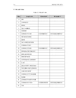
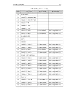
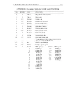
Page 14: ...ect MODEM 24 113 XTC External Clock DTE 25 142 TST Test Mode MODEM 1 3 Ordering Information T 288C Stand alone type V 34 33 6kbps modem T 288NC Rack mounted V 34 33 6kbps modem for TRS16 T 1496terbo S...

Page 15: ...1 8 TAINET NETWORK SERIES MODEM This page is intentionallyleft blank...

Page 16: ......

Page 17: ...CHAPTER 2 INSTALLATION CONTENT 2 1 Description 2 2 Unpacking 2 3 Site Requirements 2 4 Site Selection 2 5 AC Electrical Outlet Connection 2 6 Connecting With Dial Line 2 7 Connecting With Leased Line...

Page 18: ...tems are shipped with your TAINET Network Series Modem One User s Manual for TAINET Netwok Series Modem One 7 feet 2 13m modular telephone cable for connection to an RJ45 8 pin jack One 7 feet 2 13m m...

Page 19: ...eters deep in the earth Note The three grounding devices described above should be firmly placed in the earth Soil conditions should not be dry where the device is buried A metal water supply pipe con...

Page 20: ...rk Series Modem on top of another modem CAUTION To avoid overheating the TAINET Network Series Modem do not place anything within 1 inch 2 54 cm of either side of the modem and do not place the modem...

Page 21: ...dular jack The pin layout of the PHONE connector for RJ11 operation is as follows Modem PHONE Connector Pin No PHONE Jack Function CABLE Wire Color Assignment 1 N C N C 2 Not Used Black 3 Tip Red 4 Ri...

Page 22: ...X RX TX TX RX RX RX Color 2 Wire 4 Wire For 2 wire applications only pin 1 2 or pin 4 5 are required Whereas You need to connect pin 1 2 7 8 or pin 4 5 3 6 in 4 wire applications When you connect two...

Page 23: ...2 6 INSTALLATION This page is intentionallyleft blank...

Page 24: ......

Page 25: ...FRONT PANEL LCD AND MENU DRIVEN CONTENT 3 1 The Front Panel Description 3 2 The Rear Panel Description 3 3 Operating The TAINET Network Series Modem 3 4 The Menu Tree 3 5 Detailed Description of The...

Page 26: ...peration one 2 x 16 characters LCD displays and ten LED indicator lights providing a visual check of the modem s status The front panel of the TAINET T 288C T 1496terbo T 1496 and ITM 3296bis are illu...

Page 27: ...connector connected to DTE Equipment two RJ11 telephone jack one connected to dail line and the other one connected to telephone set and one RJ45 telephone jack connected to 2 wire or 4 wire leased l...

Page 28: ...upply ok DTR On for DTR signal present DSR On for DSR signal present RTS On for RTS signal present CTS On for CTS signal present TXD On for 0 off for 1 TXD signal present DCD On for received carrier s...

Page 29: ...on 8 Remote Status menu is not available before connecting and secondary channel should be set to ON C Menu Screen Example 1 Example 2 L STATUS RX Level 10dBm R CONFIG MODEM TX clock Example 3 Example...

Page 30: ...E STATUS A STATUS MENU Tx Level XX dBm Rx Level XX dBm S N Ratio XX dB F Shift X X Hz F F Shift X X Hz Delay XXXX ms N Echo XX X dB STATUS F Echo XX X dB DTE XXXXX ASY 10 Retrains XXXXX RX Baud XXXX T...

Page 31: ...ff C PROTOCOL MENU Protocol Type Direct Normal Auto MNP V42 Reliant MNP V42 MNP Type None MNP 4 MNP 5 V42 Detect 400 ms 1900 ms MNP Block Size 64 128 192 256 Break Option Break Option 0 Break Option 3...

Page 32: ...FRONT PANEL LCD AND MENU DRIVEN 3 7 B E R Test Off On...

Page 33: ...4 8 12 dB DCD On Time 0 ms 25500 ms DCD Off Time 0 ms 25500 ms Calling Tone Off On V22 Guard Tone None 550 HZ 1800 HZ below data signal level 6dB Adapt Mode Sel V 32bis Annex V 100 AA Tone Normal For...

Page 34: ...ction with mark is only available for T 1496 T 1496terbo The function with mark is only available for T 288C G CONFIG DTE MENU DTE Speed 115200 bps 76800 bps 57600 bps 38400bps 33600bps 31200bps 28800...

Page 35: ...3 10 FRONT PANEL LCD AND MENU DRIVEN Stop Bit 1 1 5 2...

Page 36: ...then the following menu tree will be shown as below Check Sum None CRC CCITT Addr Define Global User Define Setup Addr 0 255 Available for User Define If you select BI SYNC then the following menu tr...

Page 37: ...D L Timer Forever 1 Minutes 255 Minutes Dial To Leased Manu Auto Broken Discon Off On 4w Echo Cancel Off On Echo Canceller Short Long RTrip HandShake Off On V32b Fast Train Off On Note The function wi...

Page 38: ...FRONT PANEL LCD AND MENU DRIVEN 3 13 Front Lock Unlock Lock...

Page 39: ...US F Echo XX X dB DTE XXXXX ASY 10 Retrains XXXXX RX Baud XXXX TX Baud XXXX RX Freq XXXX Hz TX Freq XXXX Hz TX PowerOff X dB TR tr MR mr RS rs CS cs CD cd T t Note1 The function with asterisk mark is...

Page 40: ...10 and 26dBm S N RATIO XX dB AT S Signal to noise ratio The bigger the S N ratio the better quality of a line is A higher operating speed needs a higher S N ratio Normally the S N requirement of runni...

Page 41: ...e interference occurred This value will not be cleared automatically unless pressing the ENTER key or power off RX BAUD XXXX AT S Indication of the signalling rate of received signal For examples RX B...

Page 42: ...groups of telephone number can be obtained for an intelligent redial function RING TIMES ATS0 n Auto answer activates when detected ring count n default 2 If 108 1 DTR ON Auto Dial Ans is used for au...

Page 43: ...S44 n Pause time between auto redial IMMEDIATELY ATS44 0 This setting is limited to more than 3 minutues in Taiwan and some other countries 1 255 MINUTES default 1 minute REDIAL TIMES ATS38 n Set time...

Page 44: ...FRONT PANEL LCD AND MENU DRIVEN 3 19 1 7 seconds 2 3 seconds 3 0 seconds selections for quick connection to POS system off...

Page 45: ...ority sequence is V 42bis V 42 MNP5 MNP4 Normal However data flow control has to be used RELIANT MNP V42 AT N3 Link can be established only when both sides use V 42 V 42bis or MNP4 5 simultaneously mu...

Page 46: ...V 32 V 32bis V 34 IMMEDIATE bit2 Immediate disconnect WITH CLEAR DOWN Send clear down before disconnection DCD DCE FLOW AT Gn To activate DCE DCE flow control or not in normal mode OFF AT G0 Disable N...

Page 47: ...l or have it be sent as data to the remote modem default OFF CONNECT CODE ATWn Send back the V 42 MNP extended result code DTE SPEED ATW0 No sending back default DTE MOD EC ATW1 Sending back extended...

Page 48: ...dition DL ON OFF AT T3 For digital loop test ON OFF This test enable the received digital data demodulated and send back to match with the far end test RDL GRANT AT T4 Set for accepting remote digital...

Page 49: ...V34 14400bps 4DTCM V34 120 AT G38 Set modem speed to V34 12000bps 4DTCM V34 96 AT G33 Set modem speed to V34 9600bps 4DTCM V34 72 AT G32 Set modem speed to V34 7200bps 4DTCM V34 48 AT G31 Set modem sp...

Page 50: ...eed to BELL 212A 1200 bps DPSK BELL 103 AT G2 Set modem speed to BELL 103 300 bps FSK ORG ANS MODE ATS14 n Set modem as the originate or answer mode ORIGINATE MODE ANSWER MODE bit7 For V 34 V 32 V 32b...

Page 51: ...ly when it continuously presents longer than the set time to avoid incorrect judgement caused by transient interference default 0 6 seconds 0 25500ms 0 1 25 5 sec DCD OFF TIME ATS10 n Time period to d...

Page 52: ...ne transmit Level 0 15 dBm 0 15 dBm bit7 5 default 10 dBm POWER BACKOFF ATS43 n In V 34 operating mode the remote modem may request reduction in the transmit power level power backoff when a significa...

Page 53: ...e line then fallback or fall forward data rate automatically when the S N ratio lower or higher ON bit0 Enable OFF Disable default SIGNAL MONITOR ATS24 n Reserved Auto FB FF t bit5 4 0 1 2 3 dB Cable...

Page 54: ...reshold default 25 dB 0 49 dB V29 72 THR ATS57 n Set V 29 7200 DPSK retrain threshold for T 288C ITM 3296bis only 0 49dB default 15 dB TCM STATE ATS58 n Set trellies code state for T 288C V 34 only bi...

Page 55: ...ering modem pick up the call or not ATDnnnnn mmm can be used only when the value is correctly set default 2 sec CALL BACK ATS45 n Auto call back security function OFF bit6 Disable default ON Enable CA...

Page 56: ...ilter 60Hz Enable 60 120 180Hz jitter filter default AUTO FB FF ATS24 n The modem continuously monitors the S N ratio of the telephone line then fallback or fall forward data rate automatically when t...

Page 57: ...wer points of the transmitted signal to improve performance of PCM circuit ON bit7 Enable OFF Disable default CONSTELLATION ATS58 n Constellation expansion in V 34 operating mode add redundant higer a...

Page 58: ...dem speed is suggested to enable more effective operation When use AT command and auto baud rate detect function ON this setting will be replaced by identified speed Auto baud rate detect function can...

Page 59: ...T D3 For Modem reset DSR CONTROL AT Sn DSR signal control selection NORMAL AT S1 DSR ON after Modem handshaking FORCED ON AT S0 Force DSR in ON position DCD CONTROL AT Cn DCD signal control selection...

Page 60: ...o transmit data FOLLOW EIA CTS will be OFF only when RTS is OFF DTR RISE TIME ATS25 n Detect the time for DTR from OFF to ON default 0ms 0 1500 ms bit7 4 0 1 5 seconds OH BY DTR ATS32 n Off Hook for D...

Page 61: ...ect the terminal against any malfunction caused by the return result code from the modem RESULT FORM ATVn AT command result code format select SHORT ATV0 short form digits LONG ATV1 long form words de...

Page 62: ...YNC bit1 0 Async default HDLC SDLC HDLC SDLC BI SYNC Bisync MONO SYNC Monosync The following setup is only avlailable for ASYNC selection DATA BIT LEN ATS15 n Async data bit length 5 bit3 2 5 bits 6 6...

Page 63: ...vailable for User Define 0 255 The following setup is avlailable for both BI SYNC and MONO SYNC selection CHECK SUM Selection of the frame check sum NONE CRC 16 CODE FORMAT Selection of the data forma...

Page 64: ...DIAL ATS27 n MANU bit6 Manual control dial back up default Auto dial back up Time period which allows the determination to force the leased line been disconnected when too much retrain occurred withi...

Page 65: ...eased line automatically when leased line is recovered Broken line detection feature Disable default ON Enable Echo Canceler will be still active in 4w application of V 32 V 32b V 34 Disable default O...

Page 66: ...sync dial networks 3 AS 2L ANS V34 32b 32t Async 2W leased line answer applicable to the most of the async non compressed 2 wire leased line V 34 288 is for T 288C only Async 2W leased line originate...

Page 67: ...t the nth group is to be used for the next power on working profile operate the load user profile n FRONT LOCK Front panel lock control UNLOCK No limitation for any front panel operation default LOCK...

Page 68: ...S Indication of the carrier frequency of transmitted signal of the remot modem For V 34 only TX POWEROFF XdB AT S Indication of a reduction of transmit power level of the remot modem For V 34 only TR...

Page 69: ...3 44 FRONT PANEL LCD AND MENU DRIVEN This page is intentionallyleft blank...

Page 70: ......

Page 71: ...ompression 4 7 Configuration Profile Set up 4 8 Remote Access 4 9 Multi standard Handshake 4 10 Auto Fallback And Fall Forward 4 11 Auto Dial Back up 4 12 Auto Call Back Security 4 13 Line Status Moni...

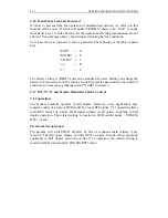
Page 72: ...es described as below DTE MODEM MODEM DTE FIG 4 1 Leased Line To make this modem operate in 2w leased line 4w leased line or dial line you need to do some settings with the Lne Type Selection under LI...

Page 73: ...V 32 V32bis V 34 mode it must provides echo cancellation because originate and answer modems occupy the same frequency band 4W leased line offers two independently unilateral transmission channel the...

Page 74: ...ry You may find the information of originate answer settings in the ORG ANS MODE column of CONFIG MODEM MENU Note that the modem will automatically determine either mode whenever you use the AT comman...

Page 75: ...s ENTER key to enter SELECT SCREEN selection 4 Use the and keys to move the desired file then press ENTER key to finish setting Now you should find a Has Been Done message on the screen During connect...

Page 76: ...dBm 10dBm 10dBm 10dBm 8 dBm 10dBm 10dBm 10dBm 8 dBm 4 dBm Dy Range 6 43 6 43 6 43 6 43 6 43 6 43 6 43 6 43 6 43 3 26 DCD off time 15 sec 15 sec 15 sec 15 sec 15 sec 15 sec 15 sec 15 sec 15 sec 5 sec A...

Page 77: ...10dBm 10dBm 10dBm 10dBm 10dBm 10dBm 10dBm 8 dBm 8 dBm 4 dBm Dy Range 6 43 6 43 6 43 6 43 6 43 6 43 6 43 6 43 6 43 3 26 DCD off time 15 sec 15 sec 15 sec 15 sec 15 sec 15 sec 15 sec 15 sec 15 sec 5 sec...

Page 78: ...ANS ANS ORG ANS ORG ANS ANS ORG ANS L L TXL 10dBm 10dBm 10dBm 10dBm 10dBm 10dBm 10dBm 4 dBm 4 dBm 10 dBm Dy Range 4 43 4 43 4 43 4 43 4 43 4 43 4 43 4 33 4 33 4 43 DCD off time 15 sec 15 sec 15 sec 1...

Page 79: ...he screen is changed to R Now the modem is working in the remote mode At this moment what you see on the local modem is exactly the same as that of the remote modem In other words there is no differen...

Page 80: ...hile using the back up line the modem periodically checks the recovery of leased lines to find the opportunity to go back to leased lines in order to save the charge of dial line To use this function...

Page 81: ...10 6 is the basic required bit error rate If this condition is not achievable leased line users should report to telephone company however it is better for dial line users to try the dial again There...

Page 82: ...It can be done by utilizing remote digital loopback RDL which makes remote modem loopback its received data To start it activate RDL in Test menu then execute BER test stated above Beware that error...

Page 83: ...he old one So don t forget the password you had entered otherwise you must use a global password XVRE to release it 4 17 ITU T V 13 and Pseudo Simulated Carrier Control V 13 operation The modem normal...

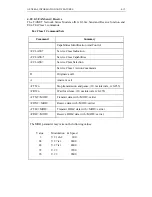
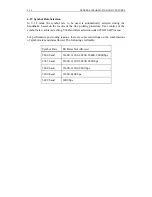
Page 84: ...ASS Service Class Selection Service Class 1 Action Commands D Originate a call A Answer a call FTS n Stop transmission and pause 10 ms intervals n 0 255 FRS n Wait for silence 10 ms intervals n 0 255...

Page 85: ...of the symbol rate is achieved setting V34 Baud Rate selection under AUXILIARY menu For perfermance and coding reasons there are some restrictions on the combinations of symbol rates and data allowed...

Page 86: ......

Page 87: ...CHAPTER 5 INSTRUCTION SETS CONTENT 5 1 AT Command Set 5 2 Dial Modifiers 5 3 Result Codes 5 4 V 25bis Auto Call Unit...

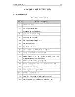
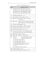
Page 88: ...1 off hook In display 0 product code 1 checksum 2 verify value Ln speaker volume 0 1 low 2 medium 3 high Mn speaker control 0 always off 1 on until DCD is detected 3 off during dialing on until DCD i...

Page 89: ...n recall factory default profile n n 0 9 Gn guard tone control 0 disabled 1 550Hz 2 1800Hz Ln line type control 0 dial line 1 2w L L 2 4w L L Mn direct mode data format 0 Async 1 Sync Qn async sync mo...

Page 90: ...DCE DCE flow control 0 disable 1 enable Hn ENQ ACK 0 none 1 to host 2 to peripheral Jn speed conversion 0 On 1 Off Kn break option 0 expedited destructive 1 expedited nondestructive 2 queued Nn data...

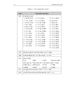
Page 91: ...0 17 V32_9600 31 V34_4800 4 B212_1200 18 V32_9600T 32 V34_7200 5 V22b_2400 19 V32b_12000T 33 V34_9600 8 V26_1200 22 V33_7200T 36 V34_21600 12 V29_4800 26 V34_19200 40 V34_2400 13 V29_7200 27 V34_24000...

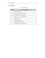
Page 92: ...rs CODE Function Description pause for 2 seconds W wait for dial tone before dialing flash hook switch for 0 5 seconds R reverse to answer mode after dialing p pulse dialing T tone DTMF dialing send c...

Page 93: ...0 MOD EC DCE ARQ MOD EC 6 NO DIAL TONE 7 BUSY 8 NO ANSWER TONE 9 CONNECT 600 10 CONNECT 2400 2400 MOD EC DCE ARQ MOD EC 11 RINGBACK TIMEOUT 12 RDL GRANTED 13 RDL DENIED 14 TRYING TO CONNECT 15 FAX 16...

Page 94: ...CE ARQ MOD EC 37 7200 MOD EC DCE ARQ MOD EC CONNECT 7200 38 CONNECT 14400 14400 MOD EC DCE ARQ MOD EC 39 REMOTE OPERATING 40 CONNECT 12000 12000 MOD EC DCE ARQ MOD EC 41 CONNECT 76800 76800 MOD EC DCE...

Page 95: ...isable 2 V 25bis Responses C VAL Modem received valid command entry D LSN Modem responses LSN when received RLN command E CNX Connection 3 V 25bis Call Failure Responses A CFIET Busy tone had been det...

Page 96: ......

Page 97: ...CHAPTER 6 MAINTENANCE 6 6 Return Procedure CONTENT 6 1 Description 6 2 Instruments 6 3 Self Test 6 4 Periodic Maintenance 6 5 Troubleshooting...

Page 98: ...FAULT 6 4 Periodic Maintenance B Be sure that the indicators function well 6 1 Description 6 2 Instruments Self test will execute whenever the modem is turned on If some faults detected the TAINET Ne...

Page 99: ...e department as soon as possible in order not to cause catastrophe You may find the contact address and phone number in the cover sheet of this manual Once the TAINET Network Series Modem malfunctions...

Page 100: ...4 V 32bis V 32 V 33 V 29 11 ms Escape sequence pause 3 bit 4 0 DTE speed bit 4 0 DTE speed 0 19200 bps 16 28800 bps 14400 bps 17 16800 bps 3 9600 bps 18 21600 bps 4 7200 bps 19 26400 bps 6 3600 bps 21...

Page 101: ...15 00001100 Binary 12 00 stop bits 1 01 stop bits 1 5 10 stop bits 2 bit 3 2 00 data bits 5 Async protocol 10 data bits 7 11 data bits 8 00 Parity None 01 Parity Even 10 Parity Odd bit 6 1 EBCDIC bit...

Page 102: ...address User Define 0 U0 Auto Baud rate Off 18 Minute 19 0 Second 20 Minute 21 01000010 Binary 66 0 S0 DSR Forced On 1 S1 DSR Normal 00 C0 DCD Forced On 10 C2 V 13 HDX bit 0 1 RDL On 1 T1 T8 LAL On b...

Page 103: ...2 bit 6 1 R1 RTS Forced On bit 7 22 11000100 Binary 196 00 L0 Speaker volumn low 10 L2 Speaker volumn midium 11 L3 Speaker volumn high 00 M0 Speaker Off 10 M2 Speaker Off always on 000 X0 Blind dial b...

Page 104: ...d 10 SM2 Reserved 1 Remote Acess ON bit 7 1 V100 25 0000 0 bit 3 0 DTR drop detection time 1111 15 bit 7 4 DTR Rise detection time 26 0 10ms RTS CTS delay time 27 00000000 Binary 0 bit 0 0 Q0 M0 Async...

Page 105: ...Flow control Xon Xoff 10 Q2 Flow control RTS CTS bit 2 0 G0 DCE DCE Flow control off 1 G1 CE DCE Flow control control on bit 4 3 00 K0 Break option 0 01 K1 Break option 1 10 K2 Break option 2 bit 5 0...

Page 106: ...bit 5 4 00 ECU0 disable 01 ECU1 V42 10 ECU2 V42bis bit 3 2 1 0 0 MNP0 disable 1 5 MNPn MNP level n 4 5 00001111 Binary 15 bit 1 0 00 A0 MNP block size 64 01 A1 MNP block size 128 10 A2 MNP block size...

Page 107: ...ip handshake disable 1 V 32bis round trip handshake enable bit 5 0 4w echo canceller disable 1 4w echo canceller enable bit 4 0 Line broken disconnect disable 1 Line broken disconnect enable 1 Power b...

Page 108: ...d rate 1 V21_300 2 B103_300 3 V22_1200 4 B212_1200 5 V22_2400 6 V23_600 7 V23_1200 8 V26_1200 9 V26_2400 12 V29_4800 15 V32_4800 16 V32b_7200T 17 V32_9600 18 V32_9600T 19 V32b_12000T 20 V32b_14400T 21...

Page 109: ...V32_9600T 19 V32b_12000T 21 V33_4800 23 V33_9600T 28 V34_28800 32 V34_7200 33 V34_9600 35 V34_16800 37 V34_26400 38 V34_12000 42 V34_33600 21 dB 2 B103_300 4 B212_1200 6 V23_600 8 V26_1200 10 V27_2400...

Page 110: ...Binary 128 0 Constellation Normal 1 Constellation Expansion bit 5 4 01 32 11 Reserved bit 3 2 1 0 59 15 dB V32b V33 7200 TCM SNR threshold V29 7200 QAM SNR threshold 58 11000000 bit 7 0 Tx Warping Of...

Page 111: ...A1 12 S REGISTER TABLE FOR T 288C ITM 3296bis This page is intentionallyleft blank...

Page 112: ...for carrier 8 Second Pause time for 9 100 ms 1 0 1S Lost carrier detect time V32 V22bis 72 14 Escape sequence pause 13 3 DTE speed 1 19200 bps 3 9600 bps 4 4800 bps 3600 bps 2400 bps 1800 bps 10 600 b...

Page 113: ...form 1 V1 code long form bit 4 bit 6 5 01 G1 550Hz guard tone 1 ORG1 Originate mode Binary 12 bit 1 0 00 stop bits 1 10 2 bit 3 2 Async protocol 01 6 10 7 bit 5 4 00 Parity none 10 odd bit 6 1 EBCDIC...

Page 114: ...10 BSC bit 3 2 00 Block check None bit 4 0 Long space disc off bit 5 0 Sync character default bit 6 0 DTE address global 0 U0 Auto Baud rate Off 1 U1 Auto Baud rate on 18 0 Minute Test timeout limit...

Page 115: ...on 000 X0 Blind dial basic 010 X2 Dial tone care 100 X4 Dial busy care bit 7 0 P0 US M B 39 61 1 P1 UK M B 33 67 23 10001010 bit 1 0 01 N1 Normal mode 11 N3 Reliable V42 MNP bit 3 2 01 9 66 0 S0 DSR f...

Page 116: ...01 W1 Extended Result code 1 10 W2 Extended Result code 2 00 Compromise EQ 0dB 10 8dB 00 Auto FB FF Off 0 Remote Acess off 1 Remote Acess on bit 7 0 AA Tone not send Normal 1 Send out AA Tone Forced o...

Page 117: ...on 1 DRL1 enable 1 DAL1 enable bit 4 0 DFB0 Secondary channel off 1 DFB1 on bit 5 0 DT Tone Dial 1 DP Pulse Dial bit 6 0 Echo protect tone Off 1 Echo protect tone On bit 7 Reserved 30 01101010 dBm 10...

Page 118: ...nc character 2 35 255 Decimal DTE address 5 Minute Time from leased to backup 37 10 Retrain Times dial backup 38 0 Times Redial Times 00100101 Binary bit 7 6 00 ECU0 disable 10 ECU2 V42bis bit 3 2 1 0...

Page 119: ...le 1 enable 45 00001000 Binary 8 0 LOCK0 Front panel lock disable 1 LOCK1 enable 1 CBK1 on bit 5 0 no ATT on RX 8 bit 7 0 Bad S N redial off 1 on bit 6 0 Modem operation bit 5 0 Speaker monitor Rx 1 S...

Page 120: ...4 FAX 9600 01 Hayes AT command 10 V 25bis command 11 I tek command bit 2 0 LCD auto on off bit 1 0 LCD always on 1 LCD always off bit 0 46 17 dB 9600 TCM SNR threshold 47 20 dB 48 dB 4800 QAM SNR thre...

Page 121: ...V22_1200 5 V22_2400 53 15 Second Hold time before call back 54 2 Second 55 18 bit 7 0 Dial Back up Speed 0 Adaptive baud rate 1 V21_300 2 B103_300 4 B212_1200 6 V23_600 7 V23_1200 15 V32_4800 16 V32b...

Page 122: ...e signaling rate and to the requirements of Group 3 data transmission For example provision must be made for minimum scan line times In band unidirectional DC1 DC3 XON XOFF flow control is mandatory f...

Page 123: ...dentification and Control A3 2 1 Service Class Indication FCLASS The current Service Class setting of a facsimile DCE is interrogated by the FCLASS command The information text response is a single va...

Page 124: ...CONNECT result code and transmits the proper training sequence in the selected mode followed by constant 1 bits until data is received from the DTE The DCE buffers data in this mode The configured fl...

Page 125: ...e data from the DTE begins to be transmitted The DCE shall check the Final Frame bit in the control field of each frame this is the 5th received bit of the second byte of each frame If the Final Frame...

Page 126: ...haracters DLE ETX and report the status of the frame reception to the DTE If the frame was received correctly FCS is OK the DCE shall return the OK result code If the frame was received in error FCS i...

Page 127: ...er send flags clear tells the CONNECT detect flags TSI frame data DCE to expect send TSI frame get TSI frame DLE ETX send FCS another frame send flags Final frame bit CONNECT DCS frame data send DCS f...

Page 128: ...er send V 21 carrier CONNECT detect flags send flags MCF frame data get MCF frame send MCF frame Final frame bit DLE ETX check FCS send FCS set OK accept FCS frame OK NO CARRIER detect loss of drop ca...

Page 129: ...frame OK AT FRH 3 CONNECT DSC frame data receive DCS send DCS frame final frame bit receive FCS set DLE ETX send FCS OK accept FCS frame OK AT FTH 3 detect loss of DTE didn t check NO CARRIER drop ca...

Page 130: ...send V 21 carrier drop carrier CONNECT send flags MCF frame data send MCF frame DLE ETX send FCS OK drop carrier final frame AT FTH 3 receives carrier send V 21 carrier CONNECT detect flags send flag...

Page 131: ...A3 10 AUXILIARY SUMMARY FOR FAX FUNCTION This page is intentionally left blank...

Reviews: