background image

- 5 -

TM

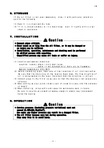
(1) Make sure that service conditions are as specified in [3. Principal Specificat

ions] in this manual.

When the oil filter is used in a hydraulic system, its selection according to

system pressure setting may turn out to be wrong in that the pressure actually
imparted to the filter may be higher than the set level.
In the case of use in a hydraulic circuit that undergoes continuous pressure
variations, consider, not system pressure setting but circuit peak pressure,
to be maximum service pressure.

(2) Starting with a low flow rate, introduce hydraulic oil into the oil filter up

to the specified flow rate.

(3) Check the housing for abnormal noise or vibrations. If any abnormality is

detected, stop the pump immediately and check for the cause.

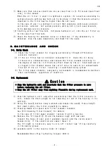
9 . M A I N T E N A N C E

A N D

C H E C K

9-1. Daily Check

(1) Check the filter element for clogging periodically through differential

pressure indicator.

(2) If the oil filter has no indicator connected to it, check the oil being

filtered on a scheduled basis and replace the filter element according to
the degree of decline in filtration effect shown by the oil. Continued use of
a clogged filter element causes the relief valve to open to let contaminants
flow out of the oil filter, resulting in a malfunctioning system.

(3) For filter paper elements, semiyearly replacement is recommended to maintain

their performance, regardless of condition.

9-2. Replacement

Caution

* Stop the hydraulic unit and ascertain that the filter pressure is zero

before replacing the oil filter.

* Keep the oil filter away from anything flammable during replacement work.

(1) Stop the hydraulic unit, and after ascertaining that the filter pressure is

zero, remove the drain plug⑨ to let remaining oil out of the housing in its
entirety.

(2) Using the case② bottom ,hang a wrench and remove the case② from a body① .

Pull down lightly the filter element③ to remove.

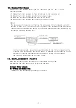
(3) Cleaning makes wire gauze wire filter elements reusable.

See [9-3 Cleaning Filter Element] for details.
In the case of filter paper element, replace it with a new one.

(4) Replace the "O"rings④ ,⑤ ,⑩ and the backup ring⑥ with new ones.

Inspect the faces of seal aren't wounded injured, and the inside aren't
became dirty. If the condition are unwell,repair it.
The "O"ring⑤ is relatively easy to slip off. Install new "O"ring carefully
in the mating groove.

(6) assemble parts in the reverse order of removal.

Recommended Drain Plug Tightening Torques: 30N・ m

Summary of Contents for TM

Page 1: ...ke sure that the user has a copy of this manual at hand for use as an operating guide Taisei Kogyo Co Ltd 6F Imaimitsubishi Bldg 3 53 11 Minamiotsuka Toshima ku Tokyo Japan Phone 81 3 6912 9922 F a x 81 3 6912 5921 No MF015 00 3 APR 28 2012 TM ...

Page 2: ...utions to be taken in case erroneous handling of the product may give rise to a dangerous situation and possibly result in a medium or minor injury or material damage are headed with Caution for particular attention These instructions must be strictly followed to prevent a serious accident that might otherwise occur C O N T E N T S 1 Product Identification 2 2 Model Code Description 2 3 Principal ...

Page 3: ... to Micro capacity application Micro capacity type is not applicable to Standard capacity application You must use the right indicator which is corresponded to the electric capacity 3 PRINCIPAL SPECIFICATIONS Permissible maximum pressure 21 0MPa Applicable fluid Mineral oils Note For phosphate and water glycol based hydraulic oils filters are different in material Service temperature range 0 90 0 ...

Page 4: ...5MPa 3 5kgf cm 2 Note that the oil filter equipped with a high pressure element 3CH 8CH 25CH have the relief valve passage blind plugged so that it has no relief valve Differential pressure type indicator optional Two types of optional indicators are available One is a visual type indicator I type whose indication turns red from green when it detects a pressure difference in filter element that ex...

Page 5: ... are no flammable Ambient temperature 0 80 2 Before connecting pipes make sure of the locations of oil inlet and outlet Be sure that the drain plug of the housing faces down The flow direction of oil is arrow marked on the cover Ascertain that the direction is correct 3 Connect pipes to the filter using care so that the housing is not excessively stressed 4 When setting up pipe joints screw a part...

Page 6: ...ntinued use of a clogged filter element causes the relief valve to open to let contaminants flow out of the oil filter resulting in a malfunctioning system 3 For filter paper elements semiyearly replacement is recommended to maintain their performance regardless of condition 9 2 Replacement Caution Stop the hydraulic unit and ascertain that the filter pressure is zero before replacing the oil filt...

Page 7: ...e In the case of wire gauze filter elements below 25 microns remove surface accumulations mostly by the above method and clean completely by ultrasonic cleaning without fail In the cleaning tank place the top and bottom of the filter element on the vibrator side alternately and clean While it depends on the capacity of the ultrasonic cleaning equipment and the amount of sludge on the element the c...

Page 8: ......

Reviews: