background image

04/01 IPN: 449-51000-03

Fault finding charts C - 11

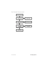
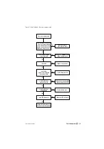
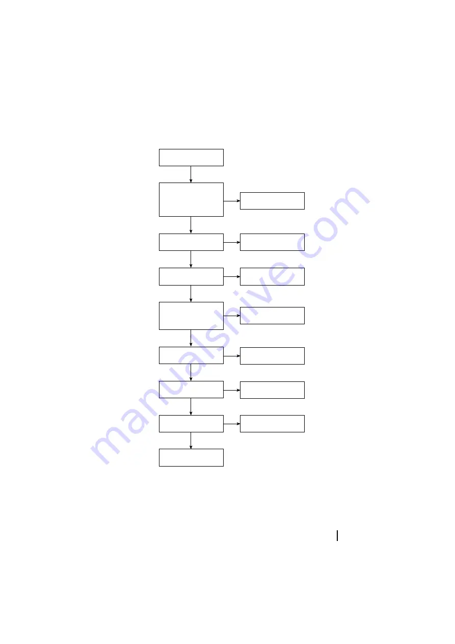
Figure C-3: Fault finding – No serial communication

Return to Tait Electronics Ltd

Customer Service Department

YES

Is the PTT jammed on?

YES

Make sure PTT is released.

Ensure loom is properly fitted

into the socket on the PCB.

Is the flexible loom

inserted correctly?

YES

NO

NO

Is the Tx/Rx

switch on the calibration

test unit set to Rx?

Set Tx/Rx switch to Rx.

NO

Leads OK?

Replace or repair leads.

NO

YES

No serial communication

NO

Is the flexible loom

end damaged?

YES

Replace flexible loom.

Make sure physical

connections are intact.

NO

YES

Are the physical connections

correct, e.g. battery charged,

comms lead inserted correctly

into the correct port on the PC,

flexible loom contacts clean, etc.?

Is the software using the

correct serial port?

Change the  COMM Port  using

Utility | Defaults option.

NO

YES

Summary of Contents for Orca 5010

Page 1: ...Tait Orca 5000 Handportable Radios Service Manual Issue 03 April 2001 IPN 449 51000 03 ...

Page 2: ...i 04 01 IPN 449 51000 03 ...

Page 3: ...04 01 IPN 449 51000 03 i Contents Part A Introduction Part B Radio specifications and circuit descriptions 00 1 1 1 0 2 34 ...

Page 4: ...ii 04 01 IPN 449 51000 03 2 34 5 6 7 5 7 8 Part C Diagnostics and fault finding 9 8 7 1 8 8 8 0 8 8 Part D Servicing the radio 7 5 5 2 0 4 5 1 5 2 0 4 1 5 5 2 0 4 0 7 7 0 0 ...

Page 5: ...04 01 IPN 449 51000 03 iii 5 0 7 0 5 3 5 3 8 8 5 8 8 2 4 2 04 0 2 4 1 2 4 0 2 4 0 0 2 4 0 0 2 4 0 Part E Battery packs and chargers 5 9 9 8 9 9 1 9 9 9 9 9 9 9 9 9 ...

Page 6: ...iv 04 01 IPN 449 51000 03 8 9 Part F Accessories 5 8 8 5 8 8 6 A 8 6 A 8 6 A 8 0 6 A 8 A 8 6 2 4 8 6 2 04 8 8 6 A 8 1 Part G Additional information 0 0 0 0 1 1 1 1 0 0 0 0 ...

Page 7: ...A P A R T Introduction Contents 1 1 ...

Page 8: ...A 2 04 01 IPN 449 51000 03 ...

Page 9: ... 5000 handportables 2 3 1 3 2 3 4 1 3 5 6 7 8 2 96 3 6 6 6 0 7 8 2 96 2 1 3 7 8 2 96 3 6 6 1 6 1 6 6 6 6 3 1 6 6 4 4 3 3 0 3 WWW technical support 0 1 5 5 111 1 2 What does this manual contain 7 3 92 1 5 6 6 3 6 6 6 What is included in the calibration service kit 3 5 7 3 96 7 3 96 8 8 8 ...

Page 10: ...1 IPN 449 51000 03 3 7 3 896 7 3 96 7 3 96 7 3 96 6 3 3 7 3 9 7 3 449 5 7 3 A8 2 8A 2 896 2 1 6 1 2 2 6 3 3 4444 44 B Programming kit 3 5 7 3 96 8 8 8 3 7 3 896 3 3 7 3 9 7 3 449 Conventions 2 1 2 bold sans serif font 4 5 Radio Model Specifications ...

Page 11: ... reserved G 336 400 MHz H 400 470 MHz I 450 530 MHz J 806 870 MHz Tx 851 870 MHz Rx K 896 941 MHz Tx 935 941 MHz Rx b Channel space IFBW 1 12 kHz Medium IFBW MB 20 25 30 kHz Channel spacing see note 1 2 10 kHz Universal IFBW UB 12 5 15 20 25 30 kHz Channel spacing c User interface 1 Elan 2 Excel 3 Eclipse 4 5010 5030 see notes 1 6 5 5035 see notes 1 6 6 5020 5040 see notes 1 6 d Air interface 1 Co...

Page 12: ...rger or Orca Multi Charger USER GUIDES Guide ENGLISH M5010 000 00 050 M5020 000 00 050 M50TK 000 00 050 GERMAN M5010 000 01 050 M5020 000 01 050 M50TK 000 01 050 FRENCH M5010 000 02 050 M5020 000 02 050 M50TK 000 02 050 EURO SPANISH M5010 000 04 050 M5020 000 04 050 M50TK 000 04 050 SOUTH AMERICAN SPANISH M5010 000 05 050 M5020 000 05 050 M50TK 000 05 050 BRAZILIAN PORTUGUESE M5010 000 08 050 M502...

Page 13: ...Orca 5000 series of handportables A 7 1 Fitting an accessory with D clip D 1 2 1 7 2 9 Fitting a non Tait accessory 1 Figure A 3 Fitting and removing a D clip to a Tait Orca 5000 handportable Installing the D clip Removing the D clip ...

Page 14: ...one and earphone TOPA AA 010 3 wire lapel microphone and earphone TOPA AA 011 Light weight single speaker headset with in line PTT TOPA AA 012 Over the head headset with noise cancelling boom microphone TOPA AA 013 Behind the head headset with noise cancelling boom microphone TOPA AA 101 Speaker microphone 10 C two function buttons with D clip TOPA AA 102 Speaker microphone 30 C heavy duty two fun...

Page 15: ...ion T952 042 USA and Canada 115 V 60 Hz input plug configuration T952 052 UK and Hong Kong 230 V 50 Hz input plug configuration Carrying accessories TOPA CA 001 Heavy duty carry case TOPA CA 002 Heavy duty holster TOPA CA 003 38 mm belt clip x 10 TOPA CA 004 Accessory port cover x 10 TOPA CA 005 55 mm belt clip TOPA CA 006 55 mm belt clip x 10 TOPA CA 101 Heavy duty carry case with D clip TOPA CA ...

Page 16: ...A 10 The Tait Orca 5000 series of handportables 04 01 IPN 449 51000 03 ...

Page 17: ... A 1 Typical anti static bench setup Warning 1 Caution CMOS devices 2 1 1 2 2 Screw head types 4 1 3 B 1 B 1 4 1 2 4 3 B 1 4 I 1 4 D 1 2 8 3 3 B 8I 8I 1 3 B D 1 2 8 Programming 2 5 6 2 1 4 3 to building earth not mains earth via 1 M series resistor conductive wrist strap conductive rubber bench mat metal frame 1 2 3 4 ...

Page 18: ...A 12 Important information 04 01 IPN 449 51000 03 ...

Page 19: ...B P A R T Radio specifications and circuit descriptions Contents 00 1 1 1 0 2 34 2 34 5 6 7 5 7 8 ...

Page 20: ...B 2 04 01 IPN 449 51000 03 ...

Page 21: ...oad impedance Rated power Distortion Response 13 Ω 500 mW 1kHz 60 deviation into 16 Ω 5 1kHz 60 deviation at rated power into 16 Ω 6 dB oct 1 3 dB cf 1 kHz 300 2550 Hz narrowband 300 3000 Hz wideband Spurious emissions to 1 GHz 1 to 4 GHz 136 470 MHz 1 to 12 75 GHz 470 MHz 57 dBm conducted and radiated 47 dBm conducted and radiated 47 dBm conducted only Group delay variation 50 µs at detected audi...

Page 22: ...io output 300 3000 Hz Trunking data deviation as per MPT1327 narrowband mediumband wideband 1 5 kHz 2 4 kHz 3 kHz Audio response below limiting in limiting above 3 kHz input for 60 deviation distortion 6 dB oct 1 3 dB cf 1 kHz 300 3000 Hz 0 dB 0 4 dB cf maximum system deviation 450 2550 Hz 35 dB oct min 5 mVrms 5 at 1 kHz Ruggedness 2 minutes into infinite VSWR Stability 5 1 VSWR all phase angles ...

Page 23: ...Ah NiMH 510g 530g 535g With TOPB500 2000mAh NiMH 550g 570g 575g Receiver Measurements as per ETS 300 086 Intermediate frequencies 21 4MHz and 455kHz Sensitivity 12dB SINAD 119dBm Sensitivity 20dB SINAD 114dBm Fixed Squelch Sensitivity 12dB SINAD or 16dB SINAD Nominal Selectivity 70dB NB 75dB WB Spurious Response 70dB Intermodulation 65dB Blocking 94dB Ultimate Signal to Noise Ratio EIA 37dB NB 42d...

Page 24: ...H 510g 530g 535g With TOPB500 2000mAh NiMH 550g 570g 575g Receiver Measurements as per ETS 300 086 Intermediate frequencies 21 4MHz and 455kHz Sensitivity 12dB SINAD 119dBm Sensitivity 20dB SINAD 114dBm Fixed Squelch Sensitivity 12dB SINAD or 16dB SINAD Nominal Selectivity 70dB NB 75dB WB Spurious Response 70dB Intermodulation 65dB Blocking 94dB Ultimate Signal to Noise Ratio EIA 37dB NB 42dB WB A...

Page 25: ...H 510g 530g 535g With TOPB500 2000mAh NiMH 550g 570g 575g Receiver Measurements as per ETS 300 086 Intermediate frequencies 21 4MHz and 455kHz Sensitivity 12dB SINAD 119dBm Sensitivity 20dB SINAD 114dBm Fixed Squelch Sensitivity 12dB SINAD or 16dB SINAD Nominal Selectivity 70dB NB 75dB WB Spurious Response 70dB Intermodulation 65dB Blocking 94dB Ultimate Signal to Noise Ratio EIA 37dB NB 42dB WB A...

Page 26: ...With TOPB500 2000mAh NiMH 550g 570g 575g Receiver Measurements as per ETS 300 086 Intermediate frequencies 21 4MHz and 455kHz Sensitivity 12dB SINAD 119dBm Sensitivity 20dB SINAD 114dBm Fixed Squelch Sensitivity 12dB SINAD or 16dB SINAD Nominal Selectivity 66dB NB 72dB WB Spurious Response 70dB Intermodulation 65dB Blocking 94dB Ultimate Signal to Noise Ratio EIA 36dB NB 42dB WB Audio Response Wit...

Page 27: ...10g 530g 535g With TOPB500 2000mAh NiMH 550g 570g 575g Receiver Measurements as per ETS 300 086 Intermediate Frequencies 45 1MHz and 455kHz Sensitivity 12dB SINAD 119dBm Sensitivity 20dB SINAD 114dBm Fixed Squelch Sensitivity 12dB SINAD or 16dB SINAD Nominal Selectivity 66dB NB 72dB WB Spurious Response 70dB Intermodulation 65dB Blocking 94dB Ultimate Signal to Noise Ratio EIA 34dB NB 40dB WB Audi...

Page 28: ...H 510g 530g 535g With TOPB500 2000mAh NiMH 550g 570g 575g Receiver Measurements as per ETS 300 086 Intermediate frequencies 45 1MHz and 455kHz Sensitivity 12dB SINAD 119dBm Sensitivity 20dB SINAD 114dBm Fixed Squelch Sensitivity 12dB SINAD or 16dB SINAD Nominal Selectivity 66dB NB 72dB WB Spurious Response 70dB Intermodulation 65dB Blocking 94dB Ultimate Signal to Noise Ratio EIA 34dB NB 40dB WB A...

Page 29: ...ith TOPB200 1500mAh NiCd 525g 545g 550g With TOPB700 1500mAh NiMH 510g 530g 535g With TOPB500 2000mAh NiMH 550g 570g 575g Receiver Measurements as per EIA Intermediate frequencies 45 1MHz and 455kHz Sensitivity 12dB SINAD 0 25µV 119dBm Sensitivity 20dB SINAD 0 40 µV 114dBm Fixed Squelch Sensitivity 12dB SINAD or 16dB SINAD Nominal Selectivity 60dB NB 65dB WB Spurious Response 65dB Intermodulation ...

Page 30: ...th TOPB200 1500mAh NiCd 525g 545g 550g With TOPB700 1500mAh NiMH 510g 530g 535g With TOPB500 2000mAh NiMH 550g 570g 575g Receiver Measurements as per EIA Intermediate frequencies 45 1MHz and 455kHz Sensitivity 12dB SINAD 0 25µV 119dBm Sensitivity 20dB SINAD 0 40µV 114dBm Fixed Squelch Sensitivity 12dB SINAD or 16dB SINAD Nominal Selectivity 60dB NB 65dB WB Spurious Response 70dB Intermodulation 65...

Page 31: ...04 01 IPN 449 51000 03 Radio specifications B 13 ...

Page 32: ...Transmitter 1 1 7 D A B2 D D 9 3 3 1 21 1 03 1 3 1 1 1 03 2 1 2 7Power Level 9 Transmit Tx audio 4 3 1 2 M 6 7Maximum Deviation Modulation Balance 9 Receiver 03 3 1 2 1 1 2 7Front End Tuning 9 4 2 4 7 B 8 B 9 1 2 2 4 2 7 B9 21 4 2 73009 2 1 1 2 1 7Squelch Thresh olds 9 7RSSI Thresholds 9 3 48444 A B 1 1 7 4 92 1 3 4 444 8 B 1 ...

Page 33: ... Rx audio 32 2 1 1 2 4 7 M 9 2 2 2 2 2 3 3 4 2 1 1 4 4 2 1 Synthesiser and VCO 1 2 1 2 1 1 4 4 4 4 70 9 1 7 9 2 2 M 7 921 7TCXO Calibration 9 Power supplies 5V DIG N 1 1 1 5V AN N 1 1 2 2 5V TX N M 1 4 1 7V5 BATT N 7V5 ACC N 1 1 7V5 SW N D 1 1 14V N 1 N D N ...

Page 34: ...B 16 Circuit descriptions 04 01 IPN 449 51000 03 4V3 DEC N N 1 1 Accessory connector interface Implications of universal band versus wideband IF filtering 1 1 1 2 3 48444 3 4 444 1 1 1 1 1 3 2 1 1 1 1 ...

Page 35: ...W 1 2 4 8 C C Q1 BC847W Q2 BC847W R1 470 R2 470 C1 100N C11 10N C2 47N R4 1K0 R3 1K0 C5 10N C6 10N C7 10N C8 10N C9 10N C10 10N C4 1N0 C3 100N LK1 LK2 Q5 BC857W Q4 BC857W R16 33 R14 4K7 R13 47K 47K 22K Q3 DTC144W 1 2 3 R12 47K R15 2K2 TP1 TP2 C15 1N0 C16 150P TP3 TP4 TP5 TP6 TP7 TP8 TP9 TP10 TP11 TP12 TP13 TP14 SK3 SMA 90DEG SKT UP TACT DOWN TACT SWITCH 1P1W 1 2 R5 2K2 R6 10 R7 10 MIC MICORPHONE 1...

Page 36: ...B 10 Radio specifications and circuit descriptions 04 01 IPN 449 51000 03 ...

Page 37: ...7W R1 470 R2 470 C1 100N C11 10N C2 47N R4 1K0 R3 1K0 C5 10N C6 10N C7 10N C8 10N C9 10N C10 10N C4 1N0 C3 100N LK1 LK2 Q5 BC857W Q4 BC857W R16 33 R14 4K7 R13 47K 47K 22K Q3 DTC144W 1 2 3 R15 2K2 TP1 TP2 C15 1N0 C16 150P TP3 TP4 TP5 TP6 TP7 TP8 TP9 TP10 TP11 TP12 TP13 TP14 SK3 SMA 90DEG SKT UP TACT DOWN TACT SWITCH 1P1W 1 2 R5 2K2 R6 10 R7 10 MIC MICORPHONE 1 V 2 GND GREEN D1 DUAL LED 1 2 RED D1 D...

Page 38: ...B 12 Radio specifications and circuit descriptions 04 01 IPN 449 51000 03 ...

Page 39: ...C P A R T Diagnostics and fault finding Contents 9 7 1 0 ...

Page 40: ...C 2 04 01 IPN 449 51000 03 ...

Page 41: ...449 51000 03 Test facilities C 3 Test facilities 1 1 1 5 3 6 D 2 1 5 5 A 5 5 5 1 5 2 O 7Shift 692 1 7 92 P7Shift 59 7 9 Q 8 1 1 2 Error codes 1 1 7 3 92 C01 C02 7 9 1 C03 7 9 2 2 2 C04 2 2 X01 3 1 1 1 2 X02 X03 4 ...

Page 42: ...C 4 Test facilities 04 01 IPN 449 51000 03 X04 3 3 2 3 X05 3 1 3 1 3 1 X06 X09 4 1 1 1 4 1 1 1 1 1 1 X31 X32 X33 X35 1 1 1 X36 8 1 1 X37 6 1 1 1 X38 8 1 ...

Page 43: ... to Rx 32 None Set radio to Tx 33 None Set transmit to low power 34 None Set transmit to mid power 135 None Set transmit to high power 35 None Set transmit to max power 36 None Set transmit to no power 137 None Activate economy mode 42 None Deactivate economy mode 43 None Read battery level 46 Returns 0 to 255 Read temperature level 47 Returns 0 to 255 Set keypad test on 50 None Set keypad test of...

Page 44: ...transistor gate bias 111 0 to 255 Set TCXO mod 112 0 to 255 Set VCO mod 113 0 to 255 Set Tx power level 114 0 to 255 Set TCXO coarse frequency 115 0 to 255 Set TCXO fine frequency 116 0 to 255 Set Rx front end tuning 117 0 to 255 Set squelch threshold 118 0 to 255 Set CTCSS modulation 120 0 to 32767 Set DCS modulation 121 0 to 32767 Set FFSK modulation 122 0 to 32767 Set Selcall modulation 123 0 t...

Page 45: ...uencies Note tttttt and rrrrrr may be up to 6 digits long Example 1 Calculating tttttt for an H band radio Example 2 Calculating rrrrrr for an H band radio Note IF depends on the radio s switching band For A B C and D bands radios the IF is 21 4 MHz For A band add the IF MHz in the formula radio uses high side injection For E F G H I J and K band radios the IF is 45 1 MHz transmit frequency MHz ch...

Page 46: ...C 8 Fault finding charts 04 01 IPN 449 51000 03 Fault finding charts 5 1 6 6 6 6 6 4 2 ...

Page 47: ...on for pins 1 to 4 OK NO Battery contacts OK Replace both battery contacts Radio cannot be switched on NO Is the battery charged YES Charge the battery Replace on off volume control switch YES Return to TEL Customer Service Department YES NO Check on off volume control switch Function for pins 1 to 4 OK NO Battery contacts OK Replace both battery contacts YES NO Check on off volume control switch ...

Page 48: ... 0 1 0 5 0 1 0 0 9 1 0 0 0 PINS CHANNELS 1 S C to GND 0 O C to GND Bottom of PCB Antenna connector 16 way selector On off volume control 1 2 3 6 5 4 YES Return to Tait Electronics Ltd Customer Service Department Replace channel selector switch Using the truth table below is channel selector operation OK Cannot change channel NO 6 3 4 1 2 0 0 0 1 3 0 0 1 0 5 0 1 0 0 9 1 0 0 0 PINS CHANNELS 1 S C to...

Page 49: ...rt on the PC flexible loom contacts clean etc Is the software using the correct serial port Change the COMM Port using Utility Defaults option NO YES Return to Tait Electronics Ltd Customer Service Department YES Is the PTT jammed on YES Make sure PTT is released Ensure loom is properly fitted into the socket on the PCB Is the flexible loom inserted correctly YES NO NO Is the Tx Rx switch on the c...

Page 50: ...ce on off volume control switch NO Is receive sense 117 dBm YES NO Is squelch operating normally 16 dB city 12 dB country YES Recalibrate squelch NO NO Reprogram radio YES NO Is the radio programmed correctly NO Is the radio in lock command 72 YES NO Does on off volume pot vary between 180 ohms to 10K between pin 3 and GND and between pin 2 and GND YES Return to Tait Electronics Ltd Customer Servi...

Page 51: ...tioning Check PTT switch YES NO Replace RF out assembly YES Check programming Are channels and frequency band information programmed correctly NO Is RF out assembly OK NO Reprogram radio YES NO Is the radio programmed correctly NO Is the radio in lock command 72 NO Return to Tait Electronics Ltd Customer Service Department Cannot transmit YES YES Is current greater than 1 5 A high power or 700 mA ...

Page 52: ...e internal microphone working Ensure loom is properly fitted into the socket on the PCB Replace internal microphone NO NO Replace flexible loom NO NO Is the flexible loom inserted correctly YES YES Is the flexible loom damaged When an external accessory is plugged in is there microphone audio for the accessory YES Return to Tait Electronics Ltd Customer Service Department No transmit audio YES Is ...

Reviews: