background image

D

PA

RT

Servicing the radio

This part describes the disassembly and reassembly of Tait Orca 

5000 handportables and the servicing of some key mechanical 
and ancillary devices. 

Information is also provided on ordering spare parts for servicing 

handportables.

Contents

Servicing the radio

Servicing the radio

Servicing the radio

Servicing the radio    .........................................................................................

.........................................................................................

.........................................................................................

.........................................................................................D-3

D-3

D-3

D-3

Screw head types  ................................................................................................... D-3

Disassembling the radio

Disassembling the radio

Disassembling the radio

Disassembling the radio    ................................................................................

................................................................................

................................................................................

................................................................................D-4

D-4

D-4

D-4

Removing the front panel from the chassis  ........................................................... D-4

Removing the shield from the chassis  ................................................................... D-5

Removing the PCB from the chassis  ...................................................................... D-6

Removing the rear panel  ....................................................................................... D-7

Replacing key mechanical and ancillary devices

Replacing key mechanical and ancillary devices

Replacing key mechanical and ancillary devices

Replacing key mechanical and ancillary devices    ............................................

............................................

............................................

............................................D-8

D-8

D-8

D-8

Replacing the lens (Orca 5020, Orca 5035 and Orca 5040) ................................... D-8

Replacing the PTT keypad ..................................................................................... D-8

Replacing the speaker ............................................................................................ D-9

Replacing the LCD display (Orca 5020, Orca 5035 and Orca 5040) ...................... D-9

Replacing the shield, user interface PCB assembly and polyester dome 
(Orca 5020, Orca 5035 and Orca 5040) ............................................................... D-12

Replacing the antenna connector, channel selector switch and volume control switch........D-12

Replacing the microphone  .................................................................................. D-12

Replacing the battery and speaker contacts  ........................................................ D-12

Replacing the tact switch ..................................................................................... D-12

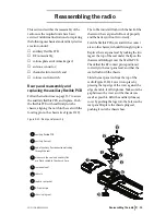
Reassembling the radio

Reassembling the radio

Reassembling the radio

Reassembling the radio    ................................................................................

................................................................................

................................................................................

................................................................................D-13

D-13

D-13

D-13

Rear panel reassembly and replacing the auxiliary flexible PCB  ......................... D-13

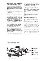
Fitting the PCB to the chassis and replacing the RF out assembly  ....................... D-14

Summary of Contents for Orca 5020

Page 1: ...y devices Replacing key mechanical and ancillary devices Replacing key mechanical and ancillary devices Replacing key mechanical and ancillary devices D 8 D 8 D 8 D 8 Replacing the lens Orca 5020 Orca 5035 and Orca 5040 D 8 Replacing the PTT keypad D 8 Replacing the speaker D 9 Replacing the LCD display Orca 5020 Orca 5035 and Orca 5040 D 9 Replacing the shield user interface PCB assembly and poly...

Page 2: ...kits D 16 D 16 D 16 D 16 Orca 5010 5030 spares kit TOPA SP 401 D 17 Orca 5035 spares kit TOPA SP 402 D 18 Orca 5020 5040 spares kit TOPA SP 403 D 19 Orca 5010 5030 Re skinning kit TOPA SP 404 D 20 Orca 5035 Re skinning kit TOPA SP 405 D 20 Orca 5020 5040 Re skinning kit TOPA SP 406 D 20 Orca 5020 5035 5040 User Interface PCB and Shield TOPA SP 407 D 20 ...

Page 3: ...yester dome Orca5020 Orca 5035 and Orca 5040 main PCB assembly antenna connector channel selector switch volume control switch microphone speaker contacts battery contacts PTT tact switch RF out assembly and auxiliary flexible PCB A list of spares kits available for servicing Tait Orca 5000 handportables is shown in Table D 1onpageD 16 Thesesparescanbeordered from your local Tait dealer Screw head...

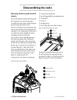
Page 4: ...e insert using a sharp scalpel blade Remove the two chassis screws at the base of the radio Figure D 1 then reattach the battery and hold the base of the radio in one hand With the other hand pull the chassis from the front panel using the base of the battery as leverage Figure D 3 At this point you can replace the following the front panel assembly thePTTkeypad PTTkeyandfunctionkeys the speaker t...

Page 5: ...ill slightly bow the shield away from the chassis Maintain pressure and insert a flat bladed screwdriver approximately 4 mm in the gap between the shield and the chassis Twist the screwdriver and the shield should rise up over the clip Figure D 4 Removing the shield sub assembly from the chassis battery pack front panel chassis shield 1 2 3 4 microphone grommet protruding from the shield grip batt...

Page 6: ...e PCB assembly and polyester dome Orca 5020 Orca 5035 and Orca 5040 Removing the PCB from the chassis Remove the knob seal which covers the anten na connector channel selector switch and volume control switch Remove the screw through the PA shield Remove the three nuts for the antenna connec tor and knobs using the supplied 8 mm long reach socket driver then remove the three ribbed lock washers Ge...

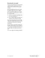
Page 7: ... the rear panel To remove the rear panel either slide the cover forward by pushing at the base with your thumbs or insert a small flat bladed screwdriver just under the notch in the base and twist Remove the rear panel seal Note that the RF contact pinnormally remainsin therear panel seal Make sure that this is not lost during disassembly Using a calibration pin lift the auxiliary flexi ble PCB co...

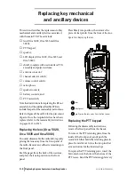
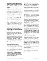
Page 8: ...ssembly instructions on pages D 13 to D 15 Replacing the lens Orca 5020 Orca 5035 and Orca 5040 You must disassemble the radio before gently prising the lens away from the front panel of the radio Remove any adhesive remaining on the front panel Peel the paper from the back of the new lens and place the lens in position on the front panel Press firmly into position then remove the piece of clear p...

Page 9: ...a 5035 and Orca 5040 Followingthedisassemblyinstructions remove the shield from the front panel and unplug the user interface loom from the main PCB Unplug the LCD display loom from the user interface PCB remove the LCD display from the shield and discard the LCD display Position the new LCD display on the shield pass the LCD loom through the gap in the shield and plug into the connector on the us...

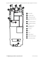
Page 10: ... chassis antenna connector channel selector switch on off volume control switch antenna connector pin placement 5 pins speaker contact pin placement channel selector pin placement 6 pins on off volume control pin placement 5 pins PTT tact switch PA can PA screw microphone placement microphone grommet placement user interface loom connector 1 2 3 4 5 6 7 8 9 10 11 12 13 ...

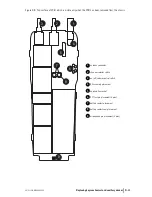
Page 11: ... only when the PCB has been removed from the chassis 1 2 3 4 5 6 7 8 9 antenna connector channel selector switch on off volume control switch RF assembly placement auxiliary flex socket PTT tact pin placement 4 pins battery contact placement battery contact seal placement microphone pin placement 2 pins 1 2 3 4 5 6 7 8 9 ...

Page 12: ...lacing the microphone make sure it isalignedwiththemarksonthePCB sinceitis polarised Refer to Figures D 8 and D 9 for the placement of the microphone The microphone should not hang over the edge of the PCB Solder it in place using a light tip soldering iron e g Weller PTR7 tip Replacing the battery and speaker contacts Following the disassembly instructions disas semble the radio to the PCB level ...

Page 13: ...e flexible PCB over and fit the contact areaonthechassis itshouldfitsnuglyinplace Replace the rear panel seal by tucking the two tags at the top of the seal under the lip on the chassis and folding it over the flexible PCB Check that the RF contact pin is positioned correctly in the rear panel seal and that the seal is flush with the chassis Slide the rear panel on from the top of the radio Figure...

Page 14: ...econefacesup Thenutsforthe two switches are black Replace the nuts making sure they are thread ed correctly before using an 8 mm long reach socketdriversetto10inchpounds Thentight en the PA screw to 2 inch pounds Using a heavy tip soldering iron e g Weller 2PTCC8 tip solder the antenna connector and two switches in place if required taking care not to damage the surrounding compo nents Replace the...

Page 15: ...o disas semblymaybehelpful Replacethetwochassis screwsatthebaseoftheradio tighteningthem to 2 inch pounds Replace the two knobs on the radio with new knobs after placing a spot of Loctite 680 on each switch shaft Make sure there is no gap between the base of each knob and the knob label by firmly pressing the top of each knob againstafirmsurface Chooseasurfacethatwill not damage the top of the kno...

Page 16: ...he numbers in the Reference column are Figure numbers in which the spares item is shown and the number in brackets refers to the numbered legend within each figure Tait Orca 5000 main PCBs are available on an exchange basis from the Customer Services Division of Tait Electronics Ltd When order ing use the following naming convention TOP XXXXX KS For example a replacement main PCB for a TOP B2620 T...

Page 17: ...5 D 2 3 365 01673 00 Insert Front Panel Logo Label 1 319 01026 00 Main RF Shield 5 D 4 1 345 00020 09 PA Screw M2x5mm Pan Torx 10 D 8 10 345 00020 11 Chassis Screw M2x8mm Pan Torx 10 D 1 3 349 00030 00 Speaker Screw 1 8x5mm Torx 10 D 7 3 352 00010 52 Channel volume Control Nut M6x7 9x3mm 20 D 12 9 352 01053 00 Antenna SMA Connector Nut 10 D 12 8 353 00010 42 Ribbed Lock Washer M6x10x0 7mm 30 D 12 ...

Page 18: ...0020 11 Chassis Screw M2x8mm Pan Torx 10 D 1 3 349 00030 00 Speaker Screw 1 8x5mm Torx 10 D 7 3 352 00010 52 Channel volume Control Nut M6x7 9x3mm 20 D 12 9 352 01053 00 Antenna SMA Connector Nut 10 D 12 8 353 00010 42 Ribbed Lock Washer M6x10x0 7mm 30 D 12 7 356 01077 00 Battery Contact Probe 10 D 9 7 360 01060 00 PTT Function Key Actuator 40 360 00010 39 Chassis Plug Seal 10 D 10 9 362 01087 00 ...

Page 19: ...00020 11 Chassis Screw M2x8mm Pan Torx 10 D 1 3 349 00030 00 Speaker Screw 1 8x5mm Torx 10 D 7 3 352 00010 52 Channel volume Control Nut M6x7 9x3mm 20 D 12 9 352 01053 00 Antenna SMA Connector Nut 10 D 12 8 353 00010 42 Ribbed Lock Washer M6x10x0 7mm 30 D 12 7 356 01077 00 Battery Contact Probe 10 D 9 7 360 01060 00 PTT Function Key Actuator 40 360 00010 39 Chassis Plug Seal 10 D 10 9 362 01087 00...

Page 20: ...tion Keypad 1 316 06765 00 Rear Panel 1 316 85133 00 PTT Function keypad retainer plate 1 345 00020 11 Screw M2x8mm SS Pan Torx Patch 2 360 01060 00 Actuator Pressel 2 362 01106 00 Rear Cover Seal 1 362 01091 01 Knob Seal 1 362 01092 02 Main Seal 1 OPP501 PHA Front Panel Assembly 1 IPN Description Quantity 311 01049 00 Channel Knob Gr 1 311 01050 00 Volume Knob Gr 1 311 03108 00 PTT Function Keypa...

Reviews: